A Coaxial Transmission Line
This example showcases a high-performing coaxial structure transmission line, effective from DC to 60 GHz. Constructed from Perfect Electric Conductor (PEC) material and Ultem 1000, this structure mimics a traditional coaxial transmission line with some variations in materials. Further details on its composition and performance are provided in the following sections.
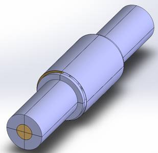
Figure 1 - Perfect line 3D structure
Dimensions
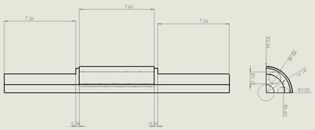
Leveraging the model's symmetry can significantly speed up the simulation process. HFWorks efficiently simulates just a quarter of the model, capitalizing on symmetry to streamline computations. This approach is particularly beneficial when the model's design permits. The accompanying figure provides detailed dimensions of the quarter structure, with all measurements precisely annotated in millimeters.
Simulation
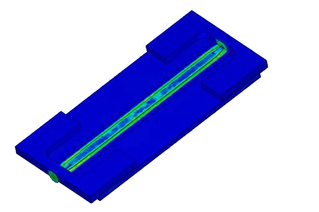
The model's design and dimensions have been refined for optimal performance. Utilizing the Scattering Parameter solver, the simulation covers frequencies from DC to millimeter waves, offering options for Fast or Discrete sweep. The Finite Element mesh is meticulously crafted to achieve high accuracy in capturing the eddy currents around curved areas.
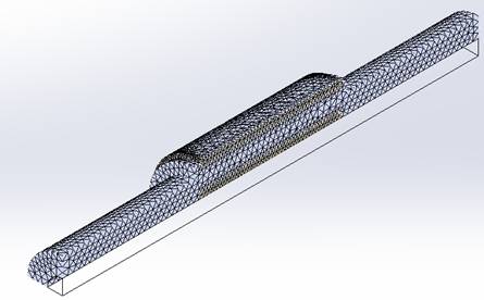
Figure 2 - Mesh of the structure
Load/ Restraint
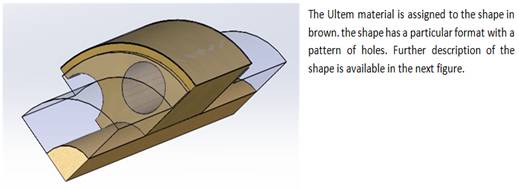
Wave propagation is analyzed in the TEM mode, with the signal boundary condition applied to the outer surface of the RF signal carrier, specifically the lateral face of the extruded cylindrical cut. The structure's lateral cylindrical shapes are designated as perfect electric conductors, ensuring accurate simulation of electromagnetic behavior.
Results
The results indicate outstanding performance across a broad frequency spectrum from DC to 60 GHz, featuring near-zero insertion loss and a return loss exceeding 20 dB.
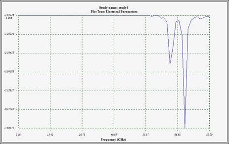
Figure 3 - Insertion loss
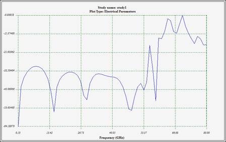
Figure 4 - Return loss
The HFWorks 3D viewer enables a detailed examination of the structure's internal field distribution, offering an in-depth view of electromagnetic interactions within.
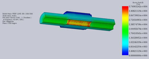
Figure 5 - Inner distribution of electric field at 40 GHz
Conclusion
This application note presents a robust coaxial transmission line engineered for exceptional performance spanning from DC to 60 GHz. Constructed with Perfect Electric Conductor (PEC) material and Ultem 1000, this structure mimics traditional coaxial lines with slight material variations. Leveraging the model's symmetry optimizes simulation efficiency, with HFWorks simulating just a quarter of the model to expedite computations. The Scattering Parameter solver covers frequencies from DC to millimeter waves, offering both Fast and Discrete sweep options. Meticulous mesh refinement ensures accuracy in capturing eddy currents around curved areas. Results demonstrate impressive performance, with near-zero insertion loss and a return loss exceeding 20 dB across the frequency spectrum. The HFWorks 3D viewer facilitates a detailed examination of the internal field distribution, providing comprehensive insights into electromagnetic interactions.