A Tilted Horn Antenna
Horn antennas, functioning effectively above 300 MHz, are integral in directing radio waves with their distinctive horn-shaped metal waveguides. Commonly utilized for calibrating other antennas, as directive components in radar technology, automatic doors, and microwave radiometry, these antennas boast a broad bandwidth, low standing wave ratio (SWR), and straightforward construction.
This example features a pyramidal horn antenna with an innovative twisted feed, adopting a four-sided pyramid form with a rectangular cross-section. Preferred for their compatibility with rectangular waveguides and their ability to emit linearly polarized waves, these antennas are meticulously modeled and evaluated using HFWorks' antenna module. Key focus areas include Scattering Parameters, internal electric field dynamics, and extensive far-field outcomes like Gain, Directivity, and Radiation patterns.
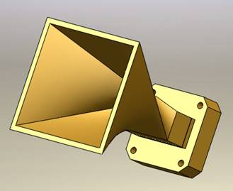
Figure 1 - Titled Horn Antenna
Simulation
The dimensions of the horn antenna are optimized for operation at 4.5 GHz, employing the antenna solver for simulation. The fast sweep frequency option is utilized, allowing for the solution at each frequency to be deduced from a single user-specified frequency. This approach significantly streamlines the simulation process, making it more time-efficient.
Solids and Materials
The antenna is constructed from copper, with the entire model designated copper material from the predefined selections in the HFWorks library. Accurately modeling the surrounding air volumes is crucial for the simulation, ensuring that the antenna's interaction with its environment is properly considered.
Loads/ Restraints
Radiation boundaries are set on the faces of the air box to facilitate accurate radiation pattern analysis. These boundaries must be strategically positioned for the optimal configuration of further radiation studies. The antenna's port is located at its rear, with the material designated as a perfect electric conductor to ensure a realistic simulation of electromagnetic behavior.
Results
A range of 3D and 2D plots are at the user's disposal, tailored to the specific requirements of the task and the parameters of interest. In antenna simulations, plotting the reflection coefficient and insertion loss is crucial for assessing matching efficiency. Subsequently, the antenna's near and far field radiation patterns can be analyzed to provide a comprehensive understanding of its performance characteristics.
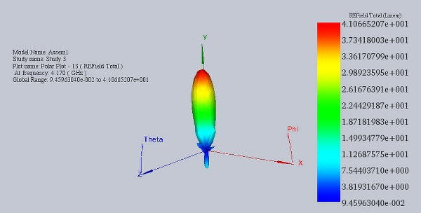
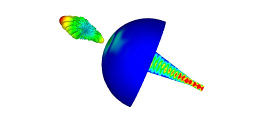
Figure 2 - Far Electric Field distribution at 1.17 GHz
The antenna achieves its best matching at 2.54 GHz, displaying an exceptionally low return loss. To further enhance the plot's smoothness, we can employ a more precise frequency step while narrowing the start and end points of the frequency interval. Additionally, we have the option to visualize the input reflection coefficient on a Smith Chart, offering a comprehensive view of impedance matching.
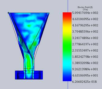
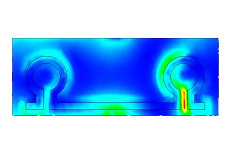
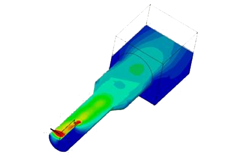
Figure 3 - Section Clipping of the antenna at 4.17 GHz
The displayed figure illustrates the electric field distribution within the horn, accomplished through the section clipping feature of HFWorks.
Furthermore, understanding the antenna's radiated power and gain is crucial. In the initial phase, plotting the reflection coefficient at the antenna's port helps identify the frequency at which nearly all power is transmitted and radiated. This information is essential for assessing the antenna's performance.
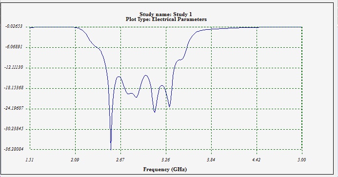
Figure 4 - Reflection coefficient at the antenna's port
Conclusion
This application note presents a detailed exploration of tilted horn antennas, essential components in various applications such as radar technology and microwave radiometry. Modeled and evaluated with precision using HFWorks, these antennas demonstrate remarkable performance at 4.5 GHz, optimized through meticulous simulation techniques. By leveraging HFWorks' antenna module, the study delves into critical parameters like Scattering Parameters, internal electric field dynamics, and extensive far-field outcomes, including Gain, Directivity, and Radiation patterns. The antenna's construction from copper and accurate modeling of surrounding air volumes ensure realistic simulation results. With comprehensive analysis tools and visualization options, the study provides valuable insights into the antenna's behavior and performance characteristics, offering a significant contribution to the advancement of antenna technology.