Prius 2004 Electric Motor
The battery and electric motor are crucial for zero-emission vehicles, prompting ongoing efforts by engineers and researchers to enhance their reliability and meet diverse user needs. In this note, we present an analysis of the 2004 Prius electric motor using EMWorks2D, accompanied by 2D and 3D CAD models. As a pioneer in mass-produced hybrids, the 2004 Toyota Prius features an Interior Permanent Magnet Synchronous Motor (IPMSM), with detailed specifications in Table 1.
| Specifications | Values |
| Rated Current | 230A RMS |
| Rated Speed | 1200RPM |
| Rated Torque | 400Nm |
| Rated Power | 50kW |
| Lamination Material | M-19 |
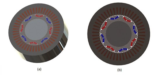
The 2004 Prius's interior PM synchronous motor features 48 slots and 8 poles within the rotor laminations core, crafted from laminated steel M-19 with a stacking factor of 0.94. It employs a 3-phase distributed winding configuration, single-layered with 9 turns per slot in series. This design enhances torque over surface-mounted motors, deriving from both permanent magnet and reluctance components. The V-shaped magnet housing boosts quadrature axis reactance, augmenting reluctance torque in harmony with the PM torque. Subsequent sections detail analyses conducted with EMWorks products.
No-Load Analysis
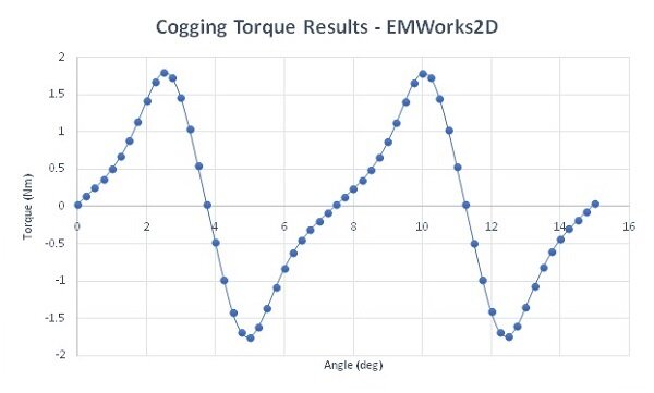
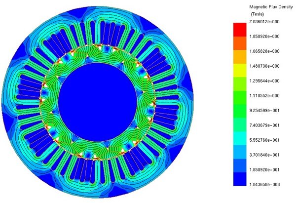
The rotor's initial position aligns the north pole axis (d-axis) with phase AA’ axis to optimize performance. Cogging torque, arising from the interaction between the ferromagnetic core and permanent magnets, is detailed in Figure 2 for the Prius IPMSM. This torque exhibits a sinusoidal pattern with a 7.5-degree period, peaking at 1.79Nm at 2.5 degrees. Figure 3 displays the magnetic flux density distribution at 0 degrees, with the windings unexcited.
Locked Rotor Analysis
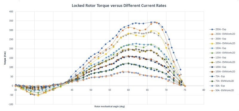
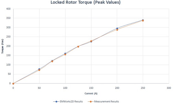
Results from various laboratories, documented in [1], [2], and [3], present the locked rotor torque across different current levels. Figure 4 compares torque outcomes at varying currents between EMWorks2D simulations and actual measurements, indicating peak torque occurs within a 60-68 degree mechanical angle. Figure 5 plots peak torque values against current.
Loaded Analysis
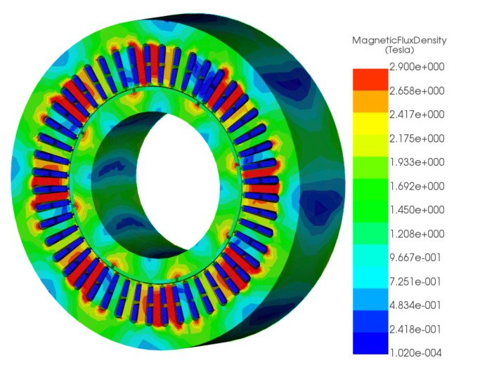
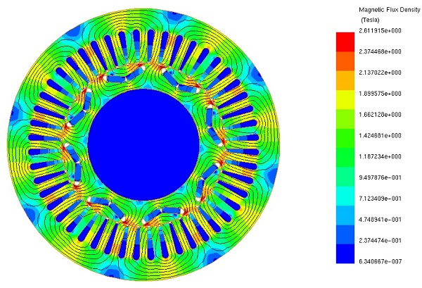
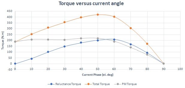
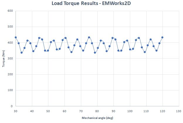
The PM synchronous machine, excited by a 230A RMS, 80Hz sine wave, operates at 1200 RPM. Figure 6 displays magnetic flux density at 0 degrees, with high field areas close to the rotor magnet bridges. An animation of the magnetic field is shown in Figure 7. In such machines, total torque combines permanent magnet and reluctance torque, maximized at a specific current angle. Figure 8 illustrates torque variations against current angle, peaking at approximately 50 electrical degrees. Figure 9 presents load torque fluctuations between 434 Nm and 339 Nm, averaging 386.5 Nm with torque ripples around 50 Nm.
Conclusion
The analysis of the 2004 Prius electric motor using EMWorks2D provides valuable insights into its design and performance. The motor, a key component of zero-emission vehicles like the Prius, features an Interior Permanent Magnet Synchronous Motor (IPMSM) with specific specifications outlined in Table 1. Through a detailed examination of its construction and operation, this study sheds light on various aspects of motor behavior, including cogging torque, magnetic flux density distribution, and torque generation under different conditions.
The no-load analysis investigates cogging torque and magnetic flux density distribution, crucial for understanding motor efficiency and performance. Locked rotor analysis compares simulated torque outcomes with actual measurements, providing validation for simulation results. Loaded analysis reveals the intricate interplay between magnetic fields, winding currents, and torque generation. Figures and animations offer visual representations of these phenomena, aiding in comprehension.