Inductive Proximity Sensor
The inductive sensor accurately detects a movable target's position by measuring PCB coil inductance variations. Correlating proximity with measured inductance is achieved through appropriate circuitry. EMS calculates PCB coil inductance at different target positions, aiding circuit designers in creating precise measurement circuits.
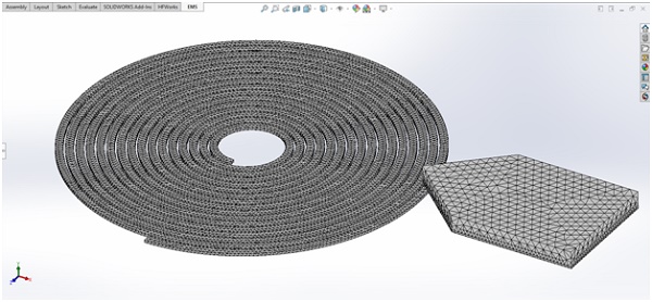
CAD model of an Inductive Proximity Sensor
Inductive sensors are widely used for position detection, operating with a coil excited by high-frequency AC current, following Faraday's law of induction. The current's amplitude is minimal, typically in the mA range. When no target is present (see Figure 1), the coil's inductance is known and computable with EMS. However, when a conductor target is positioned directly above the coil (Figure 2), the coil's inductance changes, enabling the sensor to detect the target. These sensors are effective exclusively for conductive targets.
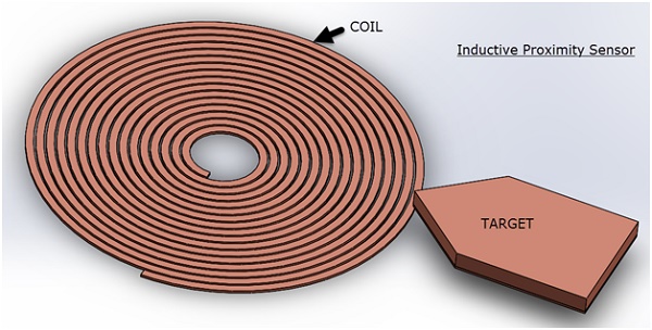
Figure 1 - Target not in the direct proximity
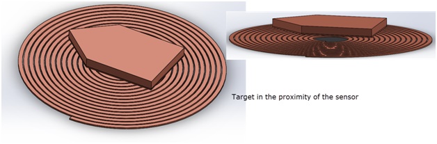
Figure 2 - Target directly above the sensor
The alteration in coil inductance may raise questions. When a metallic (conductive) target, as depicted in Figure 2 above the coil, is present, the high-frequency AC current induces eddy currents within the target. These eddy currents generate a magnetic field opposing the coil's magnetic field, leading to a reduced net field near the coil. Consequently, the coil's inductance changes, forming the fundamental principle of inductive proximity sensors. EMS calculates the coil's inductance at different target positions, elucidating this phenomenon.
EM Simulation of the Inductive Proximity Sensor
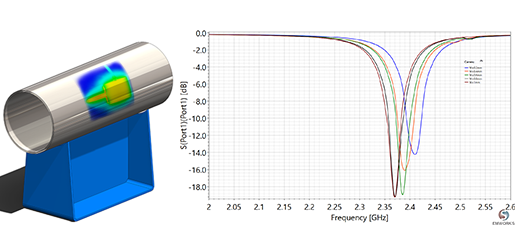
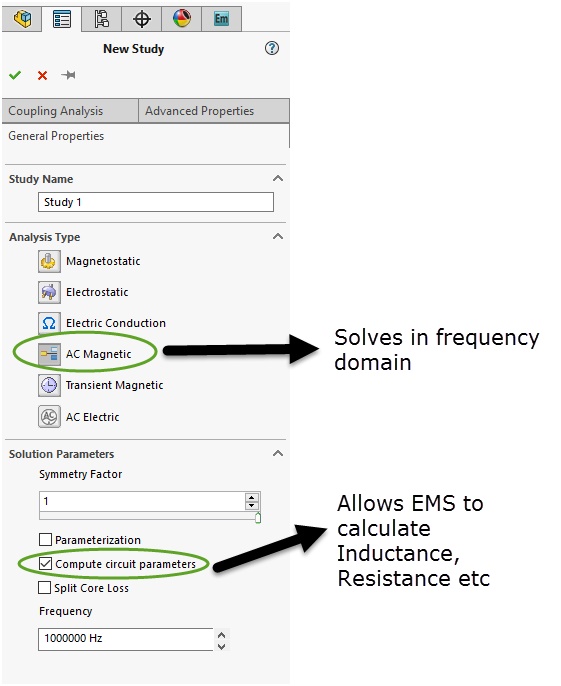
EMS employs AC Magnetic simulation to study these sensors, providing key outputs such as coil inductance, resistance, magnetic flux density, field intensity, and eddy current density. This frequency-domain solution allows for phase angle-dependent field quantities. In Figure 3, the AC Magnetic study operated at 1 MHz, with EMS accommodating frequencies up to several hundred megahertz.
Coil
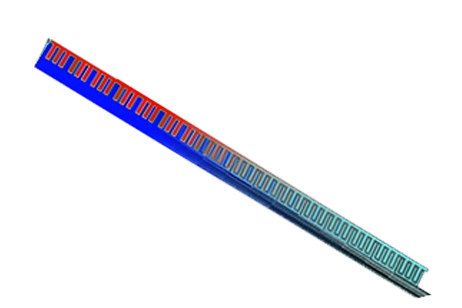
The coil is represented as a Solid Coil, with a current of 1 mA flowing as indicated in Figure 4. EMS offers modeling options for both Solid and Stranded coils, where Solid coils account for eddy currents, while Stranded coils assume their absence. In this simulation, eddy currents within the coil are disregarded, but the eddy effects are considered for the copper material used in the movable target.
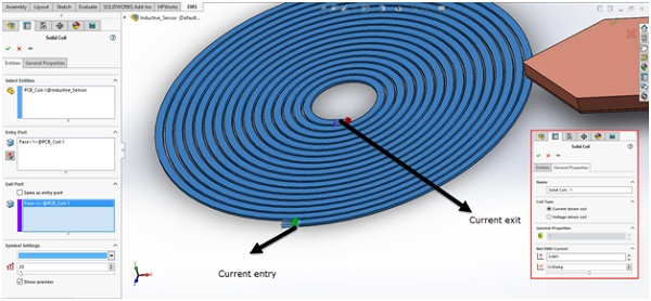
Figure 4 - Current direction in the Solid coil
Materials
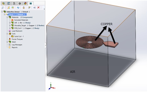
This simulation comprises three components: the coil and target are crafted from Copper, while the surrounding region is Air, as implied by its name. Figure 5 depicts the modeled components. The Air region plays a crucial role in EM simulations conducted with EMS, facilitating the extraction of field quantities within the airspace surrounding the coil and target. EMS offers a highly customizable material library featuring a wide range of commonly employed materials in Electrical Engineering.
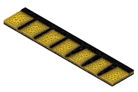
Mesh
EMS features an automatic mesh generator that seamlessly integrates with your CAD system's geometry, eliminating the need for modifications. Mesh control allows precise targeting of model regions and mesh size specification. See Figure 6 for the EMS-generated mesh.
Inductance change calculation
The Results section is categorized into three parts:
-
Coil inductance calculation
-
Coil resistance calculation
-
Field plots (Magnetic flux density, Magnetic field intensity, target eddy currents, etc.)
Inductance
Coil inductance is critical for motion detection circuit design. Figure 7 presents a table with coil inductance values at two positions: when the target approaches but is not close, and when it is directly above the coil. As the target gets closer, the inductance decreases from 1.27 to 1.07 micro Henry, representing a 15.7% reduction. These values assist engineers in designing a sensitive circuit to detect this variation.
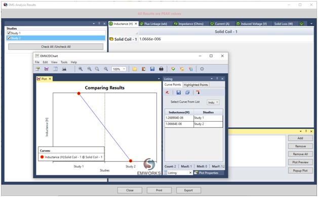
Figure 7- Inductance comparison between the 2 positions
Resistance
Coil resistance is an intrinsic property that remains constant regardless of the target's position. EMS calculates the coil resistance accurately from its geometry, resulting in a value of 0.35 Ohms, as depicted in Figure 8. It's important to note that this resistance represents the DC resistance of the coil.
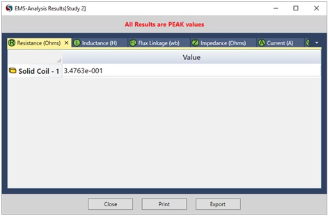
Figure 8- EMS computes the DC resistance of the coil
3D fields generated by an Inductive Proximity Sensor
Figures 9 and 10 depict magnetic field density and intensity plots for position 2 (target in proximity). Eddy currents induced on the target cause a reduction in vector sizes within the magnetic flux density plots, opposing the coil-generated field. EMS offers 3D, vector, and section plots for detailed field visualization in various scenarios.
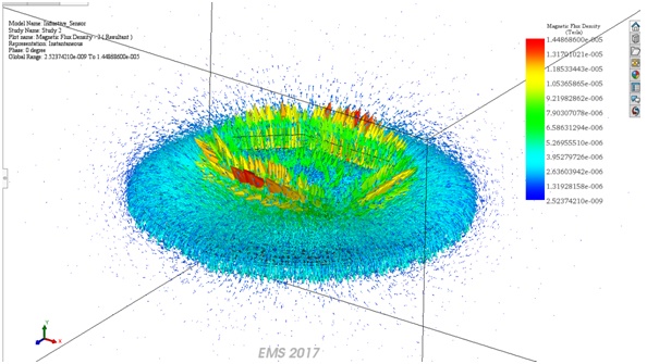
Figure 9- Vector plot of the magnetic flux density
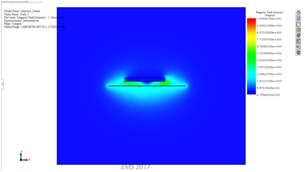
Figure 10- Section plot of the Magnetic Field Intensity
Figure 11 illustrates the distribution of eddy currents in the target when it is near the sensor (coil). Observe how the current vectors generate a flux that counteracts the flux produced by the coil.
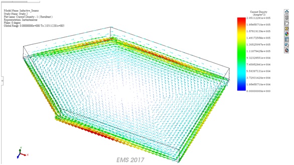
Figure 11- Eddy currents in the target
Conclusion
This application note delves into the intricacies of designing and analyzing inductive proximity sensors using electromagnetic simulation software, EMS. It meticulously demonstrates how the sensor detects a conductive target's proximity by observing changes in the coil's inductance, a phenomenon facilitated by the eddy currents induced in the target. The simulation covers the sensor's operation at high frequencies, specifically at 1 MHz, and considers various components such as the coil, target, and surrounding air. With the aid of EMS, the document outlines the process for calculating coil inductance and resistance, presenting a comparative analysis of inductance values at different target positions to showcase the sensor's sensitivity. The inclusion of magnetic field density and intensity plots further aids in understanding the sensor's electromagnetic field interactions. This comprehensive analysis underscores the importance of EMS in developing sensitive and accurate inductive proximity sensors for precise position detection.