DC Actuators
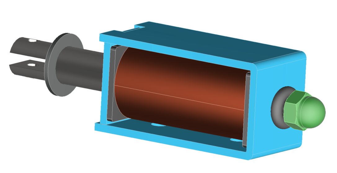
Electromagnetic actuators convert electrical power into mechanical motion, supporting linear and rotational movements. Solenoid actuators, made of permanent magnets and ferromagnetic materials, use DC current through a coil to create magnetic flux, driving the plunger linearly. This efficient design ensures precise motion control.
![DC actuator [1]](/ckfinder/userfiles/images/DC-actuator-%5B1%5D.jpg)
Figure 1 - DC actuator [1].
FEM simulation is used to study and predict the magnetic fields and the force produced by the DC actuator at each plunger position.
2D Approximation
The Finite Element Method (FEM) is available in both two-dimensional (2D) and three-dimensional (3D) variants. 3D FEM stands out for its ability to fully model the geometry of the object under analysis, capturing the intricacies of windings' end-regions with high accuracy and realism. Conversely, 2D FEM focuses on evaluating field distributions and parameters within a machine's cross-section, facilitating rapid predictions and allowing for a higher frequency of design iterations due to its shorter computation times. Although 3D FEM offers more detailed insights, it requires significantly longer processing times than its 2D counterpart.
Nonlinear magnetostatic simulation using EMWorks2D
Example 1: Planar DC actuator [2]
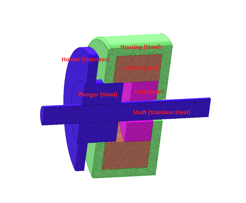
The proposed translational symmetric model is meticulously analyzed using EMWorks2D, as illustrated in Figure 2. This simulation encompasses a stator and a moving plunger, both fabricated from Silicon steel RM50, a material whose magnetic characteristics are detailed in the BH curve presented in Figure 3. Complementing these components is a copper coil, designed to conduct 1575 ampere-turns, demonstrating the model's comprehensive approach to examining electromagnetic behavior through the strategic use of varied materials.
Figure 2 - simulated model.
![BH curve of Silicon steel RM50 [2]](/ckfinder/userfiles/images/BH-curve-of-Silicon-steel-RM50-%5B2%5D.jpg)
Figure 3 - BH curve of Silicon steel RM50 [2].
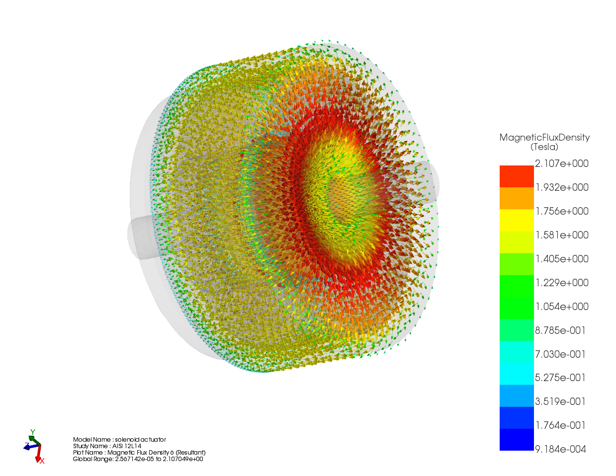
Figure 4 illustrates the model's mesh, crafted with triangular elements for precise geometry mapping. Enhanced detail is achieved around the air gap through mesh control on the edges, which produces finer mesh elements in this vital region. Subsequently, Figure 5 showcases the fringe plot of the magnetic flux, providing a visual representation of magnetic intensity distribution. Figure 6 further elucidates the model's electromagnetic dynamics by depicting the flux lines associated with the magnetic vector potential, highlighting the directional flow and concentration of magnetic fields.
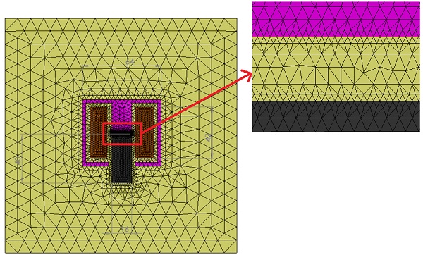
Figure 4 - Meshed model.
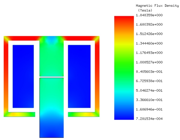
Figure 5 - Fringe plot of the magnetic flux density.
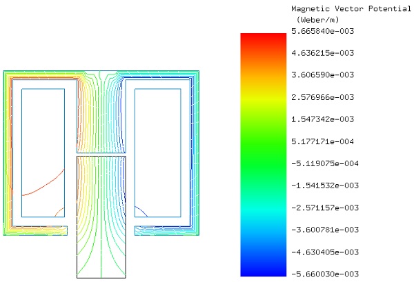
Figure 6 - Flux lines of the magnetic vector potential.
Using EMWorks2D, a parametric analysis quantifies the actuator's force against varying air gap distances—the separation between the plunger and stator. This approach allows for the adjustment of both geometrical and simulation parameters to finely tune the analysis.
Figure 7 showcases a comparison between the force calculations from EMWorks2D and those documented in reference [2]. The results display a notable concordance, affirming the reliability of the simulation. The analysis reveals that the force is inversely related to the air gap distance: as the gap diminishes, the magnetic force intensifies. This inverse relationship is fundamentally linked to magnetic reluctance, which directly scales with air gap distance, thereby providing insight into the magnetic efficiency and operational dynamics of the actuator under different spatial conditions.
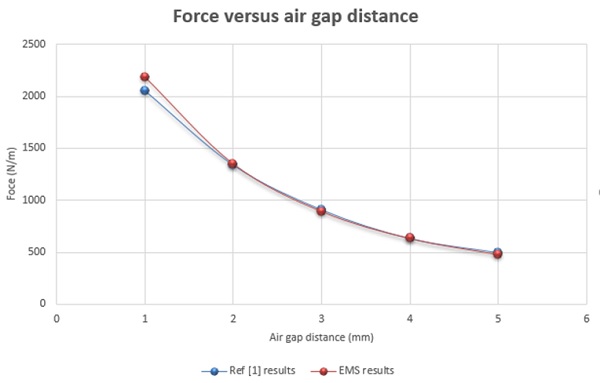
Figure 7 - Force versus air gap distance.
Example 2: Axisymmetric solenoid actuator [3]
Ref[3] introduces a linear DC actuator featuring rotational axisymmetry, analyzed under two specific conditions:
1. The construction of both the stator and the moving plunger utilizes nonlinear Carbon steel, with its magnetic characteristics illustrated by the BH curve in Figure 8.
2. The intervening gap between the moving plunger and the stationary stator is air-filled.
These scenarios enable a detailed examination of how material choices and air gaps influence the actuator's electromagnetic functionality and overall efficiency, providing valuable insights into design optimization.
![BH curve of Carbon steel [3]](/ckfinder/userfiles/images/BH-curve-of-Carbon-steel-%5B3%5D.jpg)
Figure 8 - BH curve of Carbon steel [3].
EMWorks2D facilitates the visualization and analysis of magnetic flux density, magnetic field intensity, and magnetic potential in the actuator. Specifically, Figures 9a and 9b illustrate the actuator's magnetic flux with fringe plots and line plots, respectively, showcasing the spatial distribution and flow direction of magnetic fields. Additionally, Figure 10 depicts the equipotential contours of magnetic vector potential A, providing a detailed map of magnetic potential across the actuator. These results collectively enhance the understanding of the actuator's electromagnetic dynamics.
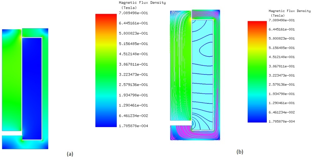
Figure 9 - Magnetic flux density a) fringe plot b) lines plot.
Utilizing EMWorks2D, the force acting on the plunger is analyzed for variations in air gap distance and DC current levels. Through parameterization, a magnetic force curve is produced, illustrating the inverse relationship between force and air gap distance—the larger the gap, the weaker the force. Figure 11 offers a side-by-side comparison of the force values calculated by EMWorks2D against those documented in reference [3], effectively demonstrating the simulation's precision in modeling the actuator's magnetic force dynamics across varying conditions.
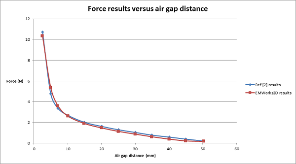
Figure 11 - Force results versus air gap distance.
Using EMWorks2D to adjust current levels and air gap distances, the software calculates the magnetic force acting within the actuator. Displayed in Figure 12, a 3D graph vividly details how the magnetic force intensifies with increased current and reduced gap distance. This graphical representation effectively highlights the relationship between these parameters and the actuator's magnetic force, providing a clear guide for enhancing actuator efficiency.
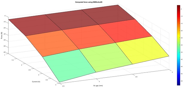
Figure 12 - Force results versus air gap distance and applied current.
Conclusion
This application note evaluates DC actuators through Finite Element Method (FEM) simulations, focusing on optimizing design for enhanced performance. DC actuators, crucial for converting electrical power into mechanical motion, rely on solenoids and permanent magnets. The study employs EMWorks2D for detailed analysis of planar and axisymmetric solenoid actuators, examining the magnetic fields and forces produced at various plunger positions.
The findings illustrate the benefits of both 2D and 3D FEM in actuator design, with 2D simulations providing quick assessments and 3D offering in-depth insights. Key results include the demonstration of an inverse relationship between the magnetic force and the air gap distance, validated against reference data. Increased current was shown to enhance magnetic force, highlighting the importance of managing air gap distances and current levels for optimal actuator efficiency.
In summary, the application note confirms the efficacy of FEM simulations in improving the design and functionality of DC actuators, underscoring the critical role of precise air gap and current control in maximizing performance.
References
[1]: https://www.electronics-tutorials.ws/io/io_6.html
[2]: Se-Hee Lee, Hong-Soon Choi, and Il-Han Park .Introducing the Virtual Air-Gap Scheme to the Kelvin Force Densities With External and Total Field. IEEE TRANSACTIONS ON MAGNETICS, VOL. 43, NO. 4, APRIL 2007
[3]: Terzova, A. I., V. M. Mateev, and I. Y. Marinova. Modelling of electromagnetic actuator with ferrofluid. CEMBEF 2013(2013): 75-78.