Electrical Busbars
In the realm of electric power distribution, a busbar, as depicted in Figure 1, serves as a vital metallic strip or bar. Typically, it resides within switchgear, panel boards, and busway enclosures, facilitating localized high-current power distribution. Additionally, these busbars play a pivotal role in connecting high-voltage equipment within electrical switchyards, as illustrated in Figure 2, and low-voltage equipment in battery banks.
Typically devoid of insulation, these busbars possess the necessary rigidity to be supported in the air by insulated pillars. This design allows for effective cooling of the conductors and the convenience of tapping into various points without necessitating the creation of new joints. Consequently, the electrical busbar serves as a central hub for collecting electrical energy at a single location.
However, it's important to note that when a fault occurs in any section of the busbar, a protective measure is taken. This involves tripping all the circuit equipment connected to that specific section to ensure rapid and complete isolation, mitigating potential hazards efficiently.
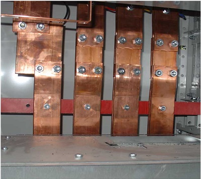
Figure 1 - Busbars used to connect electrical feeders
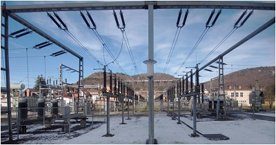
Figure 2 - High power cables connecting by busbars
Electrothermal simulation of busbar conducting DC current
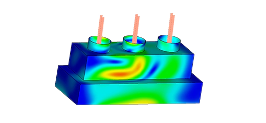
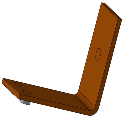
This example involves the simulation of a busbar responsible for transporting DC current from a transformer to an electrical device, as depicted in Figure 3. The flow of current through the busbar generates heat due to resistive losses, a phenomenon known as Joule heating. Joule heating is characterized by the conservation laws governing electric current and energy. Upon solving these two conservation laws, we obtain the temperature and electric field, respectively.
Electric Conduction, also referred to as current flow analysis, operates within the low-frequency electromagnetic domain and is non-time-dependent. Additionally, it pertains to objects significantly smaller than the wavelength. In contrast to Electrostatic analysis, which encompasses insulators and electric conductors, Electric Conduction focuses solely on conducting media capable of sustaining current flow.
In our specific case, the Electric Conduction solver is integrated with thermal analysis. This type of simulation resolves critical parameters such as Electric field, current density, potential, and safety factor. The thermal analysis component complements the process by considering the heat power calculated by the Electric Conduction solver, among other thermal inputs, to generate comprehensive thermal results, including temperature, heat flux, and temperature gradient.
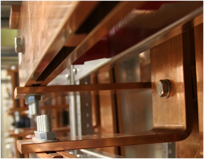
Figure 3 - Installed busbar
Simulation setup
After creating a coupled Electric Conduction and thermal study in EMS, four important steps are to be followed:
-
apply the proper material for all solid bodies
-
apply the necessary electromagnetic inputs
-
apply the necessary thermal inputs
-
mesh the entire model and run the solve
Materials
The busbar is composed of copper, while the bolts are constructed from titanium. The table below provides information about the electrical conductivity of each material.
| Components / Bodies | Material | Conductivity (S/m) |
| Bolts | Titanium | 740700 |
| Busbar | Copper | 5.998e+7 |
Electromagnetic inputs
In this study, the sole electromagnetic inputs employed are fixed voltages, as indicated in Table 2.
| Name | Fixed Voltage |
| Bolt 1 | 0.02 V |
| Bolt 2/3 | 0 V |
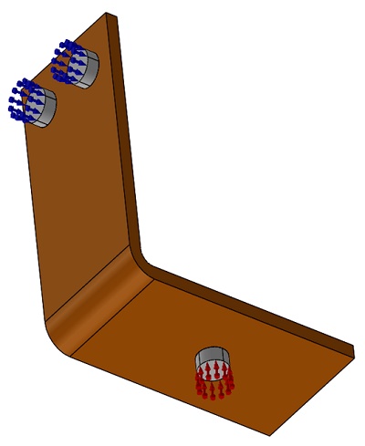
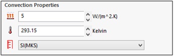
Thermal inputs
In this particular example, natural convection is applied to all surfaces except for the contact surfaces of the bolts. The ambient temperature is set at 293.15 K.
Meshing
Meshing plays an integral role in any Finite Element Analysis (FEA) simulation. Within EMS, it involves the estimation of a global element size for the model, meticulously considering factors such as its volume, surface area, and other geometric intricacies. The resulting mesh size, which encompasses the number of nodes and elements, hinges on several key factors, including the model's geometry, dimensions, specified element size, mesh tolerance, and mesh control.
During the initial phases of design analysis, where approximations may be adequate, opting for a larger element size can expedite the solution process. Conversely, for scenarios requiring heightened accuracy, a smaller element size becomes imperative.
Furthermore, the quality of the mesh can be fine-tuned through the application of Mesh Control, which can be implemented on solid bodies and faces. As illustrated in Figure 7, you can observe a finer mesh in the bolts and the regions in contact with them, highlighting the adaptability of mesh quality adjustments.
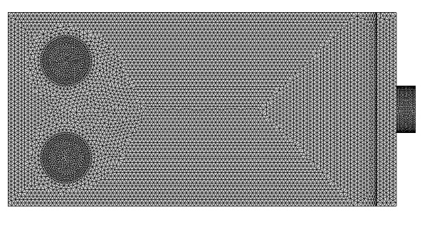
Figure 7 - Meshed Model
Electrothermal results
Figure 8 provides a visual representation of the electric field distribution within the busbar, with a notable concentration observed around the bolts. Consequently, this concentration of the electric field leads to a corresponding concentration of current density, as depicted in Figure 9.
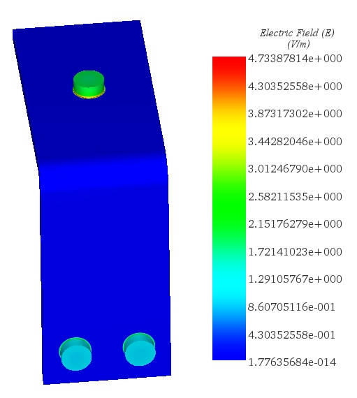
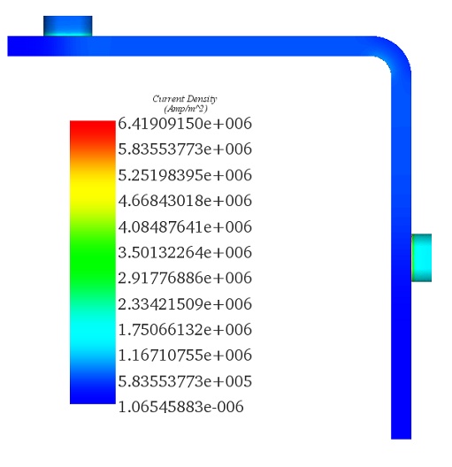
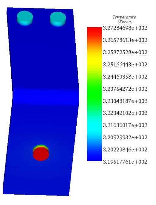
Figure 10 presents the temperature distribution within the busbar. Notably, the maximum temperature is situated at the bolt where a DC voltage of 0.02 V is applied. The temperature gradient within the busbar is substantial, with a difference of approximately 8 K between the maximum and minimum temperatures.
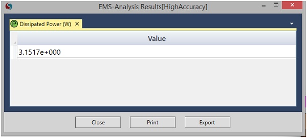
Figure 11 provides insights into the power dissipation within the busbar element, shedding light on the distribution of thermal energy within the system.
Conclusion
This application note delves into the functionality and simulation of busbars within electric power distribution systems. Busbars, metallic strips or bars, are integral in facilitating high-current power distribution across switchgear, panel boards, and busway enclosures, and in connecting high-voltage equipment in electrical switchyards. They are typically supported in the air by insulated pillars, allowing for efficient cooling and easy tapping at various points without new joints, serving as a centralized hub for electrical energy collection.
The note specifically explores the electrothermal simulation of a busbar conducting DC current, highlighting the generation of heat due to resistive losses (Joule heating) and its implications on the busbar's performance. The Electric Conduction solver, integrated with thermal analysis within EMS, is utilized to simulate and analyze critical parameters such as the electric field, current density, potential, safety factor, temperature, heat flux, and temperature gradient. This comprehensive approach allows for a detailed understanding of the busbar's electrothermal behavior, particularly around connection points like bolts where electric field and current density concentrate, leading to temperature variations.
Copper and titanium materials are chosen for the busbar and bolts, respectively, with specific attention to their conductivity. The simulation setup includes applying proper materials, electromagnetic and thermal inputs, and meticulous meshing to accurately model and analyze the busbar system. The results reveal significant temperature gradients and power dissipation patterns, emphasizing the importance of electrothermal simulation in designing and optimizing busbar systems for safe and efficient power distribution.