Magnetostriction Effect
Smart materials, including magnetostrictive ones, are vital for mitigating vibration in mechanical systems. These materials respond to signals like temperature, voltage, and magnetic fields, improving device performance by converting energy forms. Magnetostriction, where materials change shape due to magnetic fields, is key to their function. It occurs as magnetic domains rotate, causing length changes and internal strains. Positive magnetostriction leads to stretching along the magnetic field direction, with minimal volume change. As magnetic field strength increases, more domains align until saturation, enhancing performance.
Multiphysics simulation using EMS
EMS facilitates multi-physics simulations by coupling magneto-mechanical fields. Here, it's used to analyze how a constant magnetic field affects the shape of Silicon steel RM50, considering different current densities and operating regimes for a comprehensive understanding of their interaction.
CAD Model
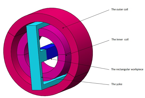
The magnetic system depicted in the figure consists of two concentric coils supplied with constant current, along with a rectangular test object surrounded by a ferromagnetic yoke. This model aims to analyze the mechanical deformation of the test object under two conditions: the linear and saturation regimes of the ferromagnetic material in the yoke and test object. Two different current densities are applied to evaluate the object's deformation.
Simulation Setup
When performing a Magnetostatic Study coupled with Structural Analysis in EMS, it's essential to adhere to the following four crucial steps consistently:
-
Apply/Select the proper material for all solid bodies
-
Apply the necessary electromagnetic inputs
-
Apply the necessary structural inputs
-
Mesh the entire model
-
Run the solver.
Materials
Table 1 outlines the properties of the materials used in the simulation. Electromagnetic equations are solved throughout the solution domain, while stress analysis focuses solely on the rectangular workpiece.
Table 1 - Material properties
|
Material |
Relative Permeability |
Electrical Conductivity (Mho/m) |
Elastic modulus (Pa) |
Poisson's Ratio |
|
Copper |
1 |
5.9980e+07 |
Not required |
Not required |
|
Air |
1 |
0 |
Not required |
Not required |
|
Silicon steel (RM50) |
* 2175 (Linear case) |
2.1186e+06 |
2.035e+011 |
0.285 |
Figure 2 shows the BH curve of the Silicon steel material (RM50).
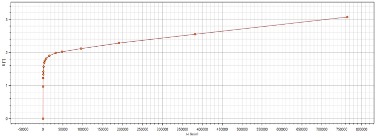 Figure 2 - BH curve of silicon steel (RM50)
Electromagnetic inputs
In this study, Two wound coils are defined as the current source of the problem.
Table 2 - Coil information
|
|
Number of turns |
Wire diameter (mm) |
Current amplitude (A) |
|
|
Wound Coil 1 |
1 |
0.91168568 mm |
47336.25 for case 1 |
|
|
Wound Coil 2 |
1 |
0.91168568 mm |
4887.5 for case 1 |
|
Mechanical boundary conditions
Fixed constraint on four edges of the rectangular workpiece (highlighted below in Figure 3)
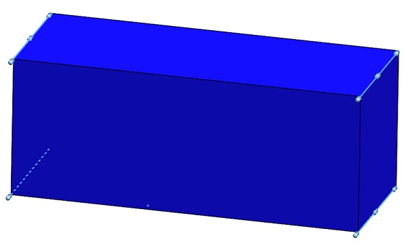
Figure 3 - Fixed constraint applied on the model edges
Meshing
Meshing is crucial in design analysis, with EMS determining a global element size based on the model's volume, surface area, and geometric features. The resulting mesh size, determined by factors like geometry, dimensions, and mesh control, impacts accuracy and solution time. In early design stages, larger elements may suffice for quicker results, but precision demands smaller elements.
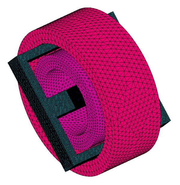
Figure 4 - Meshed model
Magneto-mechanical results
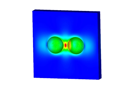
Figure 5 illustrates a comprehensive 3D view of the magnetic flux distribution throughout the entire magnetic system. This visualization accounts for the nonlinear permeabilities of both the test body and the yoke, particularly under the influence of the second applied current.
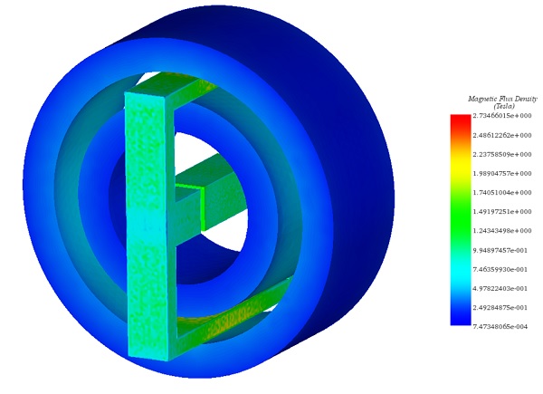
Figure 5 - Magnetic flux plot
Figure 6 demonstrates the distribution of current density within the two coils, specifically corresponding to the second scenario of applied current density.
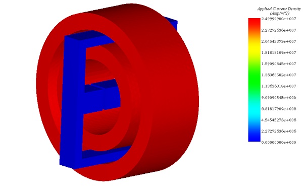
Figure 6 - Current density plot
Figure 7 visually represents the mechanical deformation experienced by the three-dimensional rectangular test object under the influence of the second applied current density. This analysis accounts for the nonlinear permeabilities of both the yoke and the test object.
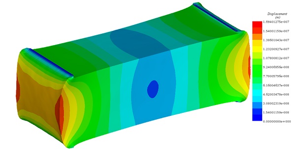
Figure 7 - Resultant displacement plot
Table 3 - Deflection of the workpiece under the two used current densities, using two different permeabilities
| Current density |
Linear permeability | Nonlinear permeability |
| J=2.5e+06 A/m^2 | 0.98 | 0.88 |
| J=25e+06 A/m^2 | 87.94 | 5.65 |
Conclusion
The application note explores the use of smart materials, particularly magnetostrictive ones, in mitigating vibration in mechanical systems. These materials respond to signals like temperature, voltage, and magnetic fields, improving device performance by converting energy forms. Magnetostriction, which involves materials changing shape due to magnetic fields, is essential to their function. EMS facilitates multi-physics simulations, allowing for the analysis of how a constant magnetic field affects the shape of materials like Silicon steel RM50, considering different current densities and operating regimes. The study involves a magnetic system comprising two coils and a rectangular test object surrounded by a ferromagnetic yoke. Results show the mechanical deformation of the test object under varying conditions, considering linear and saturation regimes of the ferromagnetic materials. EMS's meshing capabilities play a crucial role in design analysis, impacting accuracy and solution time. Larger elements may suffice for quicker results, but precision demands smaller elements. The comprehensive analysis provides insights into the interaction between magnetic fields and materials, offering valuable information for engineering design and optimization.
References
[1]:Se-Hee Lee, Xiaowei He, Do Kyung Kim, Shihab Elborai, Hong-Soon Choi, II-Han Park and Markus Zhan.2005. Evaluation of the mechanical deformation in incompressible linear and nonlinear magnetic materials using various electromagnetic force density methods. Journal of Applied Physics. Volume 97, Issue 10.