A Solar Cell
A solar cell (Figure 1), also known as a photovoltaic cell, is an electrical device that directly converts light energy into electricity through the photovoltaic effect, a combination of physical and chemical processes. It acts as a photoelectric cell, with its electrical properties like current, voltage, or resistance changing in response to light exposure. Solar cells form the foundational elements of photovoltaic modules or solar panels.
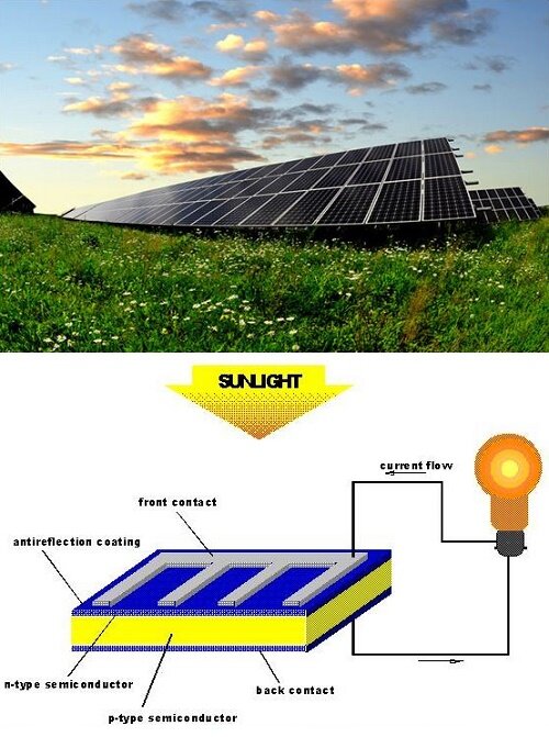
Figure 1 - Solar Cell
Solar cells, as a clean and renewable energy source, are increasingly vital across various sectors, including residential (Figure 2), industrial, public lighting, smartphone charging, and aerospace applications (Figure 3).

Figure 2 - Solar Panels used as source of energy in home

Figure 3 - International Space Station powered by solar panels
Why Simulate Solar Cells?
Simulating solar cells is crucial for several reasons: enhancing photovoltaic (PV) efficiency, optimizing design for peak performance and reliability, minimizing performance variability, forecasting manufacturing yields, and reducing production costs.
CAD Model
Innovations in solar technology introduce complexity through advanced processes and geometrical variables, such as 3D effects and intricate light paths, making simulation essential for design. The EMS Electric Conduction Module enables detailed solar cell simulation, reducing the need for extensive experimental testing.
The analyzed model is a single solar panel cell (Figure 4), featuring silicon encased between aluminum electrodes. The top electrode, a thin tapered structure, holds an electric potential of 0.6V, while the bottom, a flat rectangle, serves as ground. The analysis aims to assess the voltage drop across the silicon and the electric field and current density at the tapered electrode's end (Figure 5).
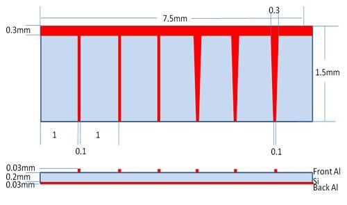
Figure 4 - Solar Cell simulated model
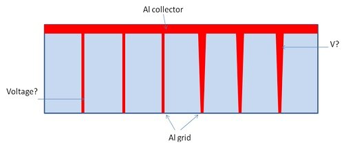
Figure 5 - Solar Cell operations
The Study
When conducting an Electric Conduction analysis with EMS, four critical steps must be adhered to: 1) Assign the correct material to all solid bodies; 2) Set the required boundary conditions, also known as Loads/Restraints in EMS; 3) Mesh the entire model; 4) Execute the solver. It's important to note that air should not be modeled in the Electric Conduction analysis.
Materials
For the Electric Conduction analysis in EMS, only the properties of electric and thermal conductivity are required, with thermal conductivity being necessary for analyses involving thermal coupling (Table 1).
Table 1 - Table of materials
| Components / Bodies | Material | Conductivity (S/m) |
| Back Electrode | Aluminum | 38.2e+006 |
| Front Electrode | Aluminum | 38.2e+006 |
| Silicon Cell | Silicon | 1.2e-005 |
Load and Restraint
In this study, only fixed voltages are applied as part of the analysis.
Table 2 - Applied Fixed Voltage
| Name | Fixed Voltage |
| Front Electrode | 0.6 V |
| Back Electrode | 0 V |
Meshing
Meshing is a crucial step in design analysis. EMS determines the global element size based on the model's volume, surface area, and geometric intricacies. The mesh size, comprising nodes and elements, is influenced by factors like geometry, element size, tolerance, and mesh control. During early design stages, larger element sizes may suffice for faster solutions, while smaller sizes offer greater accuracy. Mesh quality is further enhanced through Mesh Control (Table 3), which can be applied to solid bodies and faces. See Figure 4 for the meshed model after applying Mesh Controls.
Table 3 - Mesh control
| Name | Mesh size | Components /Bodies |
| Mesh control 1 | 2e-005 mm | Front and Back Electrode |
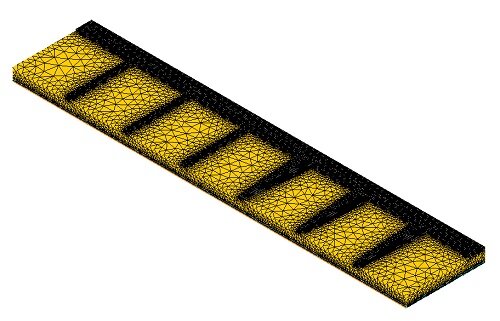
Figure 6 - meshed model
Results
Upon completing the simulation of this example, numerous results can be obtained. EMS Electric Conduction module computes and visualizes the Electric Field (Figures 7 and 8), Current Density (Figures 9 and 10), and potential (Figure 11). Additionally, a results table is generated, containing the resistance and dissipated power.
EMS provides various plot types, including fringe, line, and vector plots, as demonstrated below.
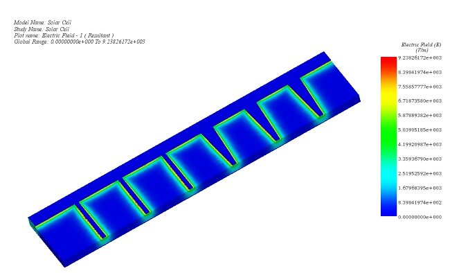
Figure 7 - Electric Field, fringe plot
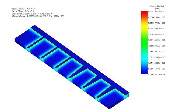
Figure 8 - Electric Field, line plot
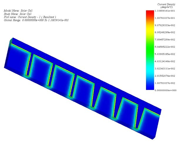
Figure 9 - Current Density, fringe plot
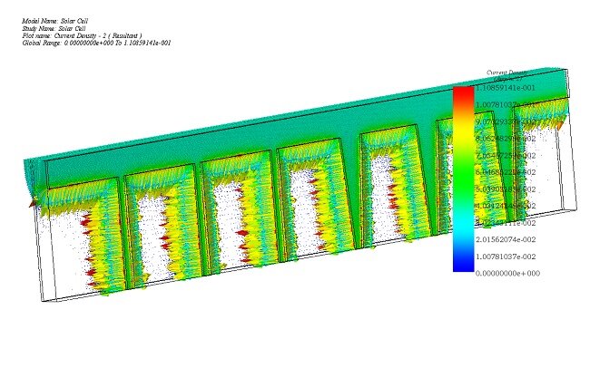
Figure 10 - Current Density, vector plot
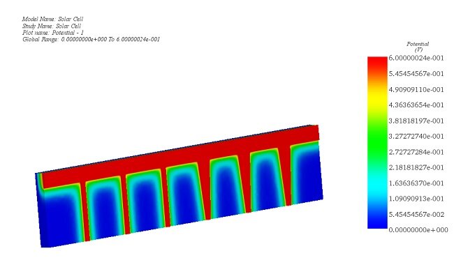
Figure 11 - Potential of solar cell
Conclusion
The application note emphasizes the critical role of solar cells in harnessing renewable energy, detailing their function as devices converting light to electricity through the photovoltaic effect. It underscores the importance of simulating solar cell designs to improve photovoltaic efficiency, optimize performance, and reduce costs, highlighting the application across various sectors including residential, industrial, and aerospace. The note presents a detailed simulation study of a solar panel cell using the EMS Electric Conduction Module, focusing on voltage drop, electric field, and current density analysis. The process involves assigning materials, setting boundary conditions, meshing, and executing solvers, with an emphasis on not modeling air in electric conduction analysis. Results from the simulation offer valuable insights into electric field distribution, current density, and potential across the cell, showcasing the simulation's capability to enhance design and performance understanding. This study exemplifies the advancements in solar technology and the necessity of simulation in the development of efficient and reliable solar energy solutions.