Magnetic Pulse Welding
Magnetic Pulse Welding (MPW) rapidly fuses metallic workpieces without excessive heat. Its versatility and precision make it invaluable across industries. Advanced simulation tools like Electro-Thermal Finite Element Analysis (FEA) help optimize the process by simulating electromagnetic fields, material behavior, and mechanical forces.
Magnetic Pulse Welding Applications Across Industries
MPW is widely used across automotive, aerospace, and electronics for joining dissimilar materials like aluminum to steel or copper to aluminum. It offers rapid joining, minimal heat-affected zones, and compatibility with materials of varying melting points, making it ideal for preserving material properties and reducing thermal distortion.
- Automotive: Joins components like heat exchangers and suspension parts.
- Oil and Gas: Bonds pipes and tubing for corrosion resistance.
- Aerospace: Welds lightweight materials for weight reduction and fuel efficiency.
- Electronics: Joins copper and aluminum conductors for efficient conductivity.
- Medical Devices: Creates hermetic seals in devices like pacemakers.
- Manufacturing: Fabricates components including heat exchangers and pressure vessels.
- Renewable Energy: Joins parts in solar panels and wind turbines for clean energy technologies.
EMWorks Solution
EMWorks facilitates the modeling and analysis of MPW, providing insights into electromagnetic forces and temperature dynamics. By coupling electromagnetic and thermal simulations, EMWorks offers a comprehensive view of the welding process, empowering engineers to optimize parameters and predict weld quality with precision, thus advancing materials joining capabilities.
Case Study: MPW of Al/Steel Sheet using One-Turn E-Shaped Coil
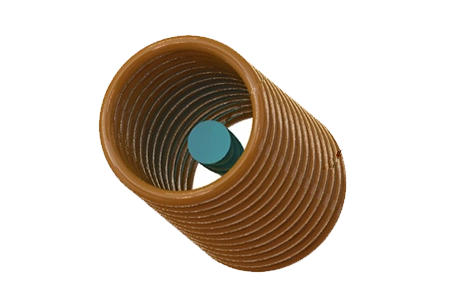
Consider a case study of Magnetic Pulse Welding (MPW) between aluminum (Al) and steel sheets using a one-turn E-shaped coil (Figures 1 & 2).
The one-turn E-shaped coil is strategically chosen to produce the essential magnetic field for MPW, ensuring uniformity and alignment with the materials.
Materials: Aluminum and steel sheets are precisely cut and cleaned to eliminate surface impurities, ensuring optimal contact and alignment for welding.
The flyer material is positioned within the coil, maintaining an initial 1 mm gap between the flyer plate and the parent plate before welding begins.
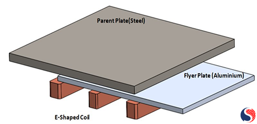
Fig. 1. 3D Model of MPW Coil Structure: One-Layer E-Shaped Flat Coil
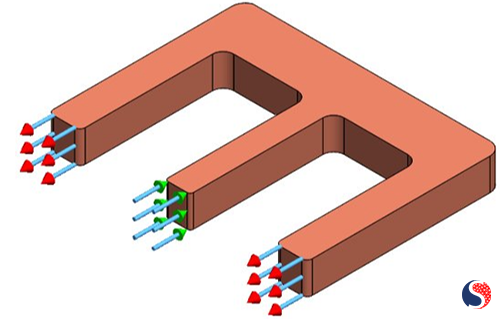
Fig. 2. E-Shaped Coil
Electrical Parameters and Circuit for MPW
The Electrical Discharge Circuit (Figure 3) powers the core of the MPW system: the high-voltage electrical pulse generator. This critical component supplies the energy needed to create a robust magnetic field, essential for propelling the flyer material. Typically operating with high-voltage, short-duration pulses, the generator's electrical parameters, such as current amplitude and duration (Figure 4), are meticulously adjusted to achieve the desired magnetic field strength. This strength directly influences the Lorentz force, which, in turn, accelerates the flyer material.
Capacitor bank (C)= 64 µF
Coil inductance= 0.02nH
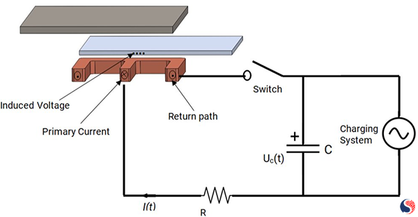
Fig. 3. The Electrical Discharge Circuit [1]
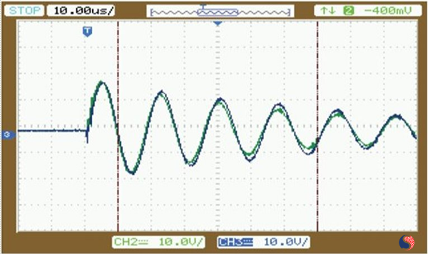
Fig. 4. Current Waveform at 9KJ Discharge Energy [2]
Thermal Input
FEA simulations aim to model and understand the thermal behavior during the welding process, requiring the consideration of various thermal parameters. Key inputs for an FEA analysis of MPW include precise material properties such as thermal conductivity, specific heat, and density (Table 1). These properties are vital for accurately simulating heat conduction and storage within the materials.
| Material | Component | Electrical Conductivity (S/m) | Specific Heat Capacity (J/Kg. K) | Mass Density (kg/m^3) | Thermal Conductivity (W/m.K) |
| Stainless Steel | Parent plate | 1.1e+06 | 490 | 7700 | 16 |
| Aluminum | Flyer Plate | 3.82e+07 | 910 | 2670 | 250 |
| Copper | Coil | 5.7e+07 | 3900 | 8900 | 385 |
Initial Temperature: Define the materials' starting temperature, impacting thermal behavior during MPW. Here, the simulation sets the initial temperature to 300 K.
Heat Transfer Coefficients: Incorporate heat transfer coefficients at material interfaces and contact points for accurate heat exchange simulation.
Thermal Boundary Conditions: Specify environmental conditions, including conduction, convection, and radiation losses. For instance, in this simulation, the convection coefficient for ambient air is set to 20 W/m^2 K.
Time-Dependent Analysis: Due to MPW's rapid nature, consider transient thermal analysis, defining pulse duration and monitoring temperature changes over time.
Mesh Density: Employ a refined mesh to capture thermal gradients and heat flow accurately, crucial for precise simulation results.
Principle & Results
The one-turn E-shaped coil is powered by a high-voltage electrical pulse, producing a robust magnetic field. This field induces an electrical current in the aluminum flyer material, propelling it towards the steel sheet.
Upon impact, the aluminum flyer material collides with the steel sheet at high velocity, causing intense localized heating and deformation. This collision and subsequent heat facilitate the formation of a metallurgical bond between the aluminum and steel sheets.
Current density distribution
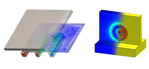
Understanding the current flow in the coil is crucial for optimizing the process and improving weld quality. Figure 5 illustrates current density distribution across the aluminum sheet and coil, highlighting areas of concentration and variation. These regions indicate strong electromagnetic forces driving rapid acceleration. High current density leads to localized heating and deformation, vital for metallurgical bond formation.
Fig. 5. Current Density Distribution inside the Aluminum Sheet and the Coil
Temperature Distribution
Understanding the temperature distribution within the aluminum flyer, as revealed by Finite Element Analysis (FEA), is crucial for grasping the thermal dynamics of Magnetic Pulse Welding (MPW).
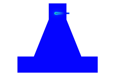
Figure 6 illustrates the temperature distribution across the flyer material, highlighting the region of highest temperature. Typically, this corresponds to areas experiencing intense electromagnetic forces, resulting in rapid heating upon impact.
FEA analysis also encompasses time-dependent results, crucial for capturing transient thermal effects inherent in MPW's rapid process.
Interpreting the temperature distribution informs optimization of the MPW process, facilitating adjustments to parameters like pulse duration and current amplitude to potentially enhance weld quality.
Fig. 6. Temperature Distribution inside the Aluminum Sheet
Conclusion
The case study demonstrates the successful MPW of an aluminum and steel sheet using a one-turn E-shaped coil. The process results in a strong and reliable metallurgical bond between dissimilar materials. This application showcases the versatility and effectiveness of MPW in joining materials with differing properties and has potential applications in various industries, including automotive, aerospace, and electronics, where dissimilar material joining is a common requirement. Further optimization and fine-tuning of parameters can lead to enhanced weld quality and efficiency in specific applications.
References
[1] Huaiqing Zhang, Zhiyuan Yang & Lianglu Ren, Experimental investigation on structure parameters of E-shaped coil in magnetic pulse welding
[2] Rajesh Kumar, Subhanarayan Sahoo, Biswanath Sarkar, Anurag Shyam; Development of electromagnetic welding facility of flat plates for nuclear industry