What is Resonant Wireless Power Transfer?
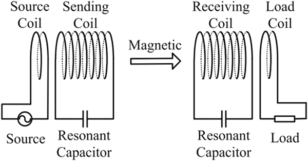
Resonant Wireless Power Transfer (RWPT), developed by MIT in 2008, enhances Wireless Power Transfer (WPT) by utilizing compensation capacitors in both transmitter and receiver. This technology nullifies impedance imaginary parts, enabling higher output power and efficiency compared to traditional WPT. RWPT is widely applied in appliances, wearable gadgets, mobile phones, and electric vehicle chargers, offering superior performance even at mid-range distances relative to coil size.
CAD Model
In this application note, a WPT system [2] is studied using EMWORKS EMAG. The system is made of two copper-printed coils. Figure 2 shows the simulated wireless system while Table 1 contains the main dimensions of the model. Later, we will add resonant capacitors to change the system from a WPT to RWPT and study the data resulting from such a change.

| External Coil | Interior Coil | |
|---|---|---|
| Inner Diameter | 27.7 mm | 11.64 mm |
| Outer Diameter | 41.3 mm | 16.14 mm |
| Inter-Traces Distance | 1.4 mm | 0.3 mm |
| Length of the Trace | 1.6 mm | 0.5 mm |
| Thickness of the Traces | 40 um | 40 um |
Table 1. Main Dimensions of the RWPT System
Using the EMWORKS EMAG module of EMWorks, we investigated the following RWPT issues:
- Circuit parameters of the simulated RWPT including R and L matrices,
- Coupling coefficient versus air gap and alignment,
- Efficiency versus frequency and geometry configurations,
- Comparison of EMWORKS EMAG results against Powersim results.
Parametric Analysis
Using the AC Magnetic module of EMWORKS EMAG, the coil parameters including self and mutual inductances, AC resistances, and coupling coefficient are computed versus different air gap distances and alignments. These parameters are then used to compute the resonant capacitance and efficiency of the system.
Table 2 contains the AC inductance and resistances for an air gap of 15 mm.
| External Coil | Interior Coil | |
|---|---|---|
| Self Inductance M (H) | 1.774798e-006 | 1.281031e-006 |
| Mutual Inductance L1(H) | 1.207742e-007 | 1.207742e-007 |
| Self Resistance R (Ohm) | 3.410545e-001 | 6.161653e-001 |
| Mutual Resistance Rm(Ohm) | 1.920747e-003 | 1.920747e-003 |
Table 2. Circuit Parameters Computed by EMWORKS EMAG
From the above circuit parameters, the coupling coefficient $$ K = \frac{M}{\sqrt{L_1 L_2}} \tag{1} $$ between primary and secondary coils is computed. The greater is k the higher is the transmitted magnetic flux from the emitter to the receiver winding; hence, the efficiency is directly proportional to the coupling coefficient [3].
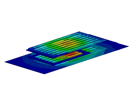
In addition to the above circuit parameters, the magnetic field and flux are computed. Figures 3a) and 3b) show the cross-section plots of the magnetic flux density results at 2 mm and 40 mm of air gap size, respectively. Clearly, the magnetic flux around the interior coil, i.e. receiver, is higher with an air gap of 2 mm compared to 40mm. Namely, 40 to 80 micro-Tesla versus 18 micro-Tesla for 2 and 40 mm, respectively.
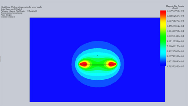
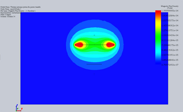
Fig. 3. Magnetic Flux Results, a) Air Gap 2 mm, b) Air Gap 40 mm
The plots of the mutual inductance M and the coupling coefficient k versus the distance between the coils are shown in Figure 4. Clearly, M and k are inversely proportional to the distance separating the coils. Furthermore, with the help of the popular closed-form solution of the mutual inductance M, the inverse proportionality is cubic in nature since $$ M = \frac{\pi \mu_{0} N_{1} N_{2} R_{1}^{2} R_{2}^{2}}{2 D^{3}} \tag{2} $$
. Consequently, to achieve a good coupling coefficient, the coils must be as close as possible. How close? Well, it depends on the level of the coupling desired.
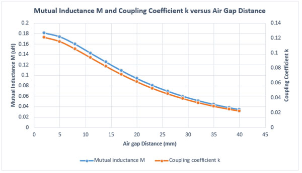
Fig. 4. Mutual Inductance M and Coupling Coefficient k Results vs Air Gap Distance
The above conclusion is also applicable to the induced voltage, under open circuit operation, in the receiver coil, as shown in Figure 5.
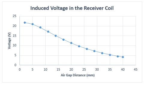
Fig. 5. Induced Voltage in the Receiver Coil vs Air Gap Distance
The results of both mutual inductance M and coupling coefficient k, shown in Figure 6, are inspected versus axial alignment using another parametric study in EMWORKS EMAG. The coupling between the coils drops only when the misalignment becomes larger than 15 mm. Hence, the studied system can operate at the same efficiency in a short range of misalignments up to 15 mm. This behavior can be attributed to the small size of the receiver.
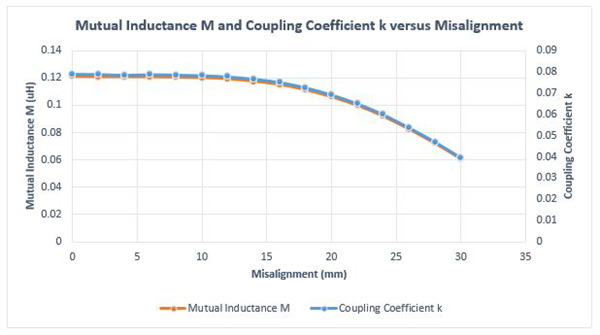
Fig. 6. Mutual Inductance M and Coupling Coefficient k Results vs Misalignment
Similarly, the induced voltage in the receiver coil is almost constant when for a misalignment less than 15mm and sharply decreases thereafter, as shown in Figure 7.
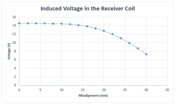
Fig. 7. Induced Voltage in the Receiver Coil vs Misalignment
Figure 8 illustrates an animation of the magnetic flux density versus different misalignments. The magnetic flux density that reaches the receiver coil is almost constant up to a certain level of misalignment.
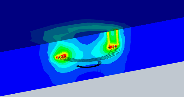
Fig. 8. Animation of the Magnetic Flux vs Different Misalignment
EMWORKS EMAG Circuit-Coupling Analysis
In the above investigated WPT system, the coupling coefficient is relatively low even at small air gap and aligned conditions. To illustrate the limitation of the WPT, we compute its efficiency as per the equation: $$ \eta = \frac{P_{\text{out}}}{P_{\text{in}}} = \frac{I_{\text{load}} R_{\text{load}}}{I_{1} V_{1} \cos \theta} \tag{3} $$ , where V1 is the input voltage, I1 is the current in the primary side, ![]() is the phase between current and voltage, Iload is the current in the load, Rload and is the resistance of the load.
is the phase between current and voltage, Iload is the current in the load, Rload and is the resistance of the load.
EMWORKS EMAG circuit simulator is used to model the equivalent circuit of the simulated system as illustrated in Figure 9. Windings 1 and 2 are the coils of the WPT system. The input voltage is 2.5 V / 13.58MHz (phase shift is 0deg) and the load is a 10 Ohm resistance.
AC Magnetic module of EMWORKS EMAG coupled to the circuit simulator are used to solve the WPT system. The transmitter and receiver are maintained at an aligned position and an air gap of 15 mm. The coupling coefficient is 0.08 at these conditions, as shown in Figure 4.
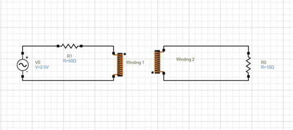
Fig. 9. The Simulated Circuit of the Studied WPT System
Table 3 contains the current results in the windings computed by EMWORKS EMAG. Using the formula (3), the efficiency of the studied system is 0.17%, which is indeed low.
| Current Computed by EMWORKS EMAG | |
|---|---|
| Winding 1 | 4.891836e-003 - j 1.479600e-002 |
| Winding 2 | -5.844385e-004 + j 1.333585e-003 |
Table 3. Current Results Computed by EMWORKS EMAG
To improve its efficiency, resonant capacitors are added to the WPT system making it into a RWPT. In the following paragraphs, we shall compute the efficiency of the RWPT and compare it to that of a WPT system.
Figure 10 shows the new simulated circuit modeled using EMWORKS EMAG circuit simulator. The resonant frequency is 13.58MHz while the resonant capacitors are respectively 77.26 pF and 114.42 pF computed based on the famous formula: $$ \omega_{0} = \frac{1}{\sqrt{LC}} \tag{4} $$
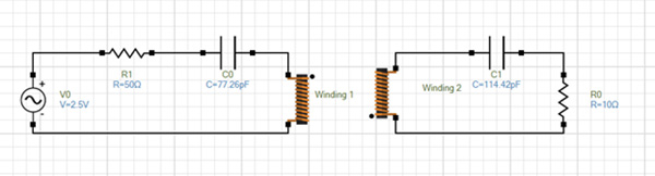
Fig. 10. Resonant Circuit of Simulated RWPT System Created Using EMWORKS EMAG Simulator
The input and output power of the studied RWPT system are computed versus frequency. Both input and output power show peak values at the resonant frequency, as illustrated in Figure 11.
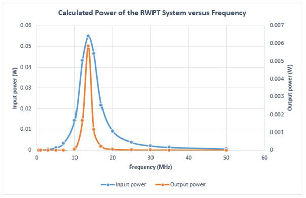
Fig. 11. Input and Output Power Results vs Frequency
Figure 12 shows the efficiency of the RWPT system versus different frequencies. The efficiency is maximum at the resonant frequency. Without resonant capacitors, the efficiency is around 0.17% while it is close to 11% when the resonant capacitors are used. This proves that the resonant circuit helps in improving efficiency, especially for applications with low coupling coefficients.
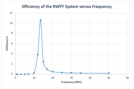
Fig. 12. Efficiency vs Frequency
The impact of the load and the air gap distance on the efficiency of the RWPT system is investigated in the following section.
Figure 13 contains the efficiency results versus the air gap distance. The efficiency has a maximum value of around 19% in the range of 2 to 7 mm of air gap distance. It drops as the distance between the coils becomes larger, i.e. inversely proportional to the distance. Nonetheless, it is still more efficient than the WPT system, even at 30mm.
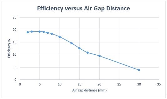
Fig. 13. Efficiency vs Air Gap Distance
The load is varied from 1 Ohm to 50 Ohm and the efficiency of the simulated system is computed using the circuit quantities generated by EMWORKS EMAG, as shown in Figure 17. The efficiency rises until reaching a maximum of 11% at a load of 10 Ohm then decreases. Therefore, the load must be carefully selected.
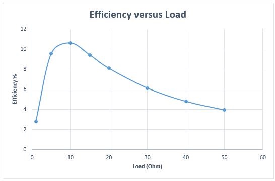
Fig. 14. Efficiency versus load
Comparison of EMWORKS EMAG Against Powersim [4] Results
In this section, the results computed by EMWORKS EMAG are compared to those obtained from and Powersim. The RWPT circuit is modeled in Powersim. Figure 15 shows the equivalent circuit of the system in Powersim. The parameters of the coupled inductor, used to model the wireless coils in Powersim, are given by EMWORKS EMAG, as shown in Table 2.
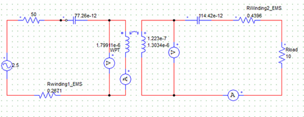
Fig. 15. Equivalent Circuit of RWPT System in Powersim
Figure 16 shows the comparison of the computed efficiency calculated via EMWORKS EMAG and Powersim. Clearly, the results show a very good agreement; actually matching results.
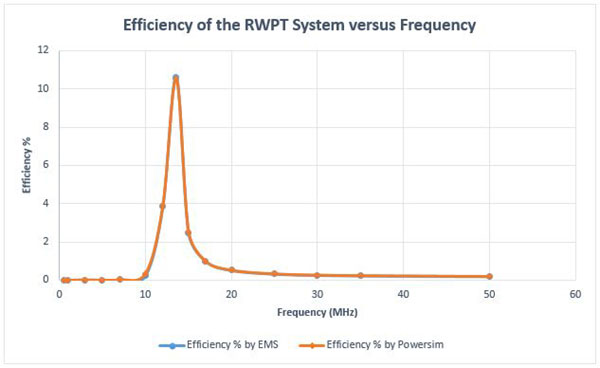
Fig. 16. Efficiency Results Comparison
The system response as a function of frequency is analyzed using Powersim and the results are plotted in Figure 17. Bode diagram shows that the amplitude output curve has a maximum value of -16dB around the resonant frequency.
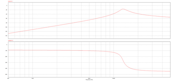
Fig. 17. Bode Diagram of the System Extracted from Powersim
Conclusion
In this application note, we began by evaluating a Wireless Power Transfer (WPT) system, finding its efficiency lacking even at close coil distances. Introducing two resonant capacitors transformed the WPT into a Resonant Wireless Power Transfer (RWPT) system, showcasing its superiority. However, efficient operation requires careful selection of the load. In the final analysis, we compared EMWorks simulation results for the RWPT system with those obtained using commercial power software Powersim, achieving a perfect match in efficiency.
References
[1]https://www.cambridge.org/core/journals/wireless-power-transfer/article/limitations-of-wireless-pow…
[2] https://commons.und.edu/cgi/viewcontent.cgi?article=3344&context=theses
[3] https://iopscience.iop.org/article/10.1088/1757-899X/53/1/012026/pdf