Wireless power transfer technology
Wireless power transfer is pivotal in modern life, offering convenience and flexibility. It boosts safety by minimizing electrical hazards and device damage, surpassing traditional wired charging. Yet, it presents design hurdles. This analysis scrutinizes key challenges across two WPT applications.
![General Block Diagram of WPT System for EV Charging [1]](/ckfinder/userfiles/images/general-block-diagram-of-wpt-system-for-ev-charging-%5B1%5D-30-05-2023.png)
Design Challenges of Wireless Power Transfer Technology
WPT technology poses several significant design challenges related to the charging process, primarily encompassing the following aspects:
-
The effect of air gap distance on the WPT efficiency
-
The effect of misalignment on the WPT efficiency
-
Electromagnetic Interference and Compatibility
-
The size and weight of the charger
-
The generated losses and Heat
-
The effect of the shielding material on the field distribution
-
Design adaptability and integration to power applications
Wireless charger for Implantable Pacemaker Application
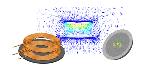
The model investigated [2] employs inductive coupling to recharge a pacemaker battery. Illustrated in Figure 2, the simulated setup comprises transmitter and receiver coils, alongside two aluminum plates and ferrite cores. Operating at a low frequency of 20kHz to adhere to EMF standards poses efficiency challenges for WPT. To enhance efficiency, aluminum plates, and ferrite cores are integrated into the design.

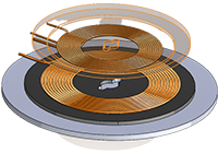
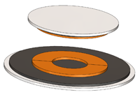
Fig. 2. 3D Model of WPT Design used in Pacemaker Application
Air Gap and Misalignment Effect on Field Distribution
To evaluate the effect of air gap distance and the misalignment on the magnetic field distribution, a parametric AC Magnetic analysis is used.
The following animation plots show the variation of the magnetic flux density for the different scenarios.
Fig. 3. Animation of the Magnetic Flux vs Airgap
Fig. 4. Animation of the Magnetic Flux vs Lateral Misalignment
Fig. 5. Animation of the Magnetic Flux vs Angular Misalignment
Air Gap Effect on Coil Parameters (R, L, and K)
One of the primary challenges is improving the efficiency of the inductive wireless power transfer system which increases with the coupling coefficient of the transmitter-receiver coils. This coefficient depends in turn on the resistance and the inductance of the used coils and it is defined by the following relation:
![]()
The following figures show the variation of the coil and coupling parameters versus the air gap distance between the transmitter and receiver sides.
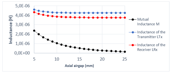
Fig. 6. Self and Mutual Inductances Results versus Air Gap
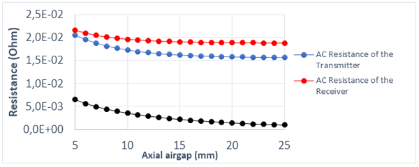
Fig. 7. AC Resistance Results versus Air Gap
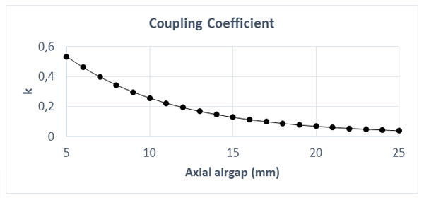
Fig. 8. Coupling Coefficient versus Air Gap
Shielding Effect on Field Distribution
Shielding is pivotal in wireless power transfer systems, containing and directing electromagnetic fields. It confines fields to desired regions, optimizing efficiency. Shielding materials concentrate, reflect, or deflect fields, enhancing coupling between transmitter and receiver coils. Simulated scenarios demonstrate shielding's role in improving effectiveness and efficiency, controlling field distribution, and minimizing energy loss. Field distribution in the WPT design reveals metallic shielding's efficacy in confining and concentrating fields between transmitter and receiver coils.
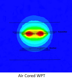
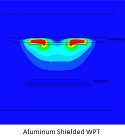
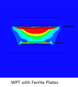
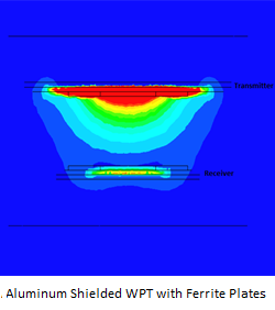
Fig. 9. Magnetic Flux Density Distributions with and without Shielding
A second visualization of the field distribution within the human body with and without the shielding is shown in the following plots:
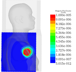
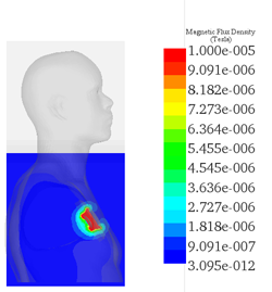
Fig. 10. Magnetic Flux Density Distributions with and without Shielding across the Human Body
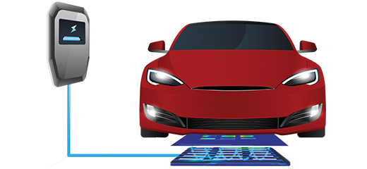
Wireless Power Charger for Electric Vehicle Application
The second WPT design is a wireless charging system for an electric vehicle made of a double-sided bipolar pad which is presented by two overlapped coils for transmitter and receiver sides made of 5 turns each and operates at the frequency of 85 kHz. The coils are carried by Ferrite support bars and shielded with Aluminum plates.
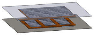
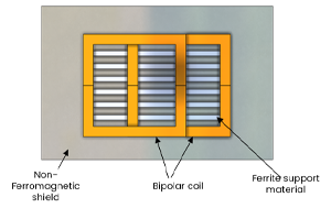
Fig. 11. 3D Design of Bipolar Pad for WPT EV Charger
The following figure shows the EMS Equivalent circuit used for the LCC Compensation Network presented in [3].
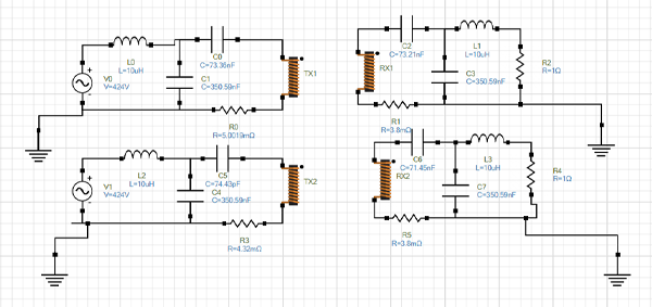
Fig. 12. Equivalent EMS Circuit Schematic for LCC Network
Shielding Effect on Field Distribution
The wireless power transfer (WPT) system's frequency significantly influences its efficiency, range, size, and compatibility. Higher frequencies entail higher energy losses and shorter ranges but enable compact designs. Lower frequencies offer longer-range power transfer but demand larger components. Choosing the optimal frequency is crucial to prevent interference and comply with regulations, balancing performance and practicality. Analyzing the operating frequency's impact on efficiency using a parametric AC Magnetic study with circuit coupling yielded the following insights:
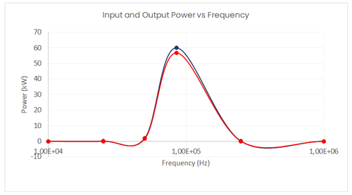
Fig. 13: Input and Output Power versus Frequency
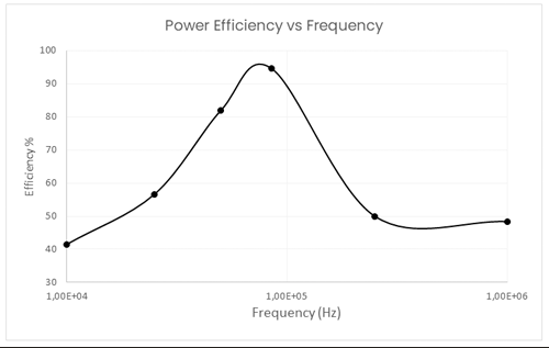
Fig. 14. Power Efficiency versus Frequency
The results obtained enabled the determination of the resonant frequency of the investigated WPT design, which operates at 85kHz. This frequency corresponds to a maximum power efficiency of 96%, calculated based on the maximum input and output power values.
The following animation plot shows the vector distribution of magnetic flux lines between the transmitter and receiver WPT sides.
Fig. 15. Vector Plot Animation of the Magnetic Flux Density
Heat and Loss Analysis
An investigation of the loss quantities generated within the studied WPT device allowed us to compute and visualize the different loss distributions across the Aluminum shielding, Ferrite bars, and copper coils, as shown below.
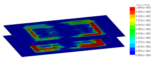
Fig. 16. Solid Loss Distribution in the Al Shield
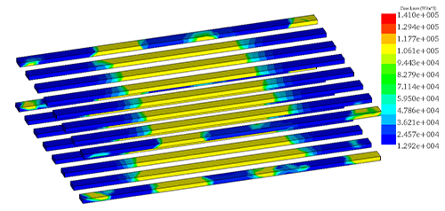
Fig. 17. Core Loss Distribution in the Ferrite Support
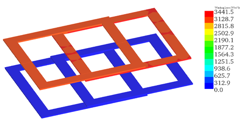
Fig. 18: Winding Loss Distribution in the Coils
Lastly, the heat generated is determined by the temperature distribution throughout the entire WPT design, reaching a maximum steady-state temperature of 67°C.
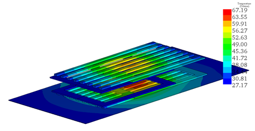
Fig. 19. Temperature Distribution across the WPT System
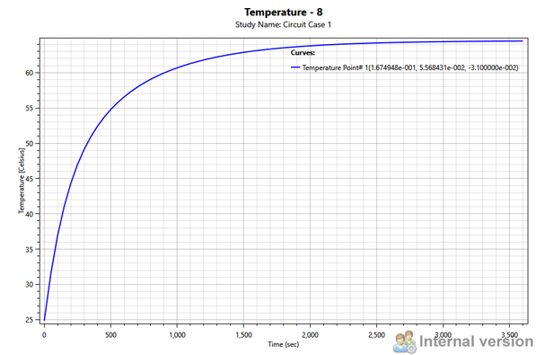
Fig. 20. Temperature Variation versus Time
Conclusion
Wireless power transfer technology is continuously advancing, with ongoing research and development endeavors dedicated to enhancing efficiency, range, and standardization. As this technology progresses, we anticipate witnessing its increased adoption and integration across diverse industries and everyday applications. Through this application note, an investigation of the main design challenges of the WPT system for two different applications allowed us to analyze the performance of this technology over various design scenarios.
References
[1]- https://eps.fiu.edu/inductive-power-transfer-systems/
[2]- Wireless power transfer for a pacemaker application, Vladimir Vulfin, Shai Sayfan-Altman & Reuven Ianconescu, Journal of Medical Engineering & Technology