A Voice Coil Actuator
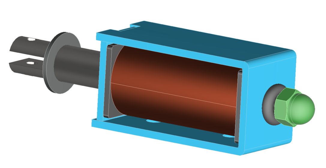
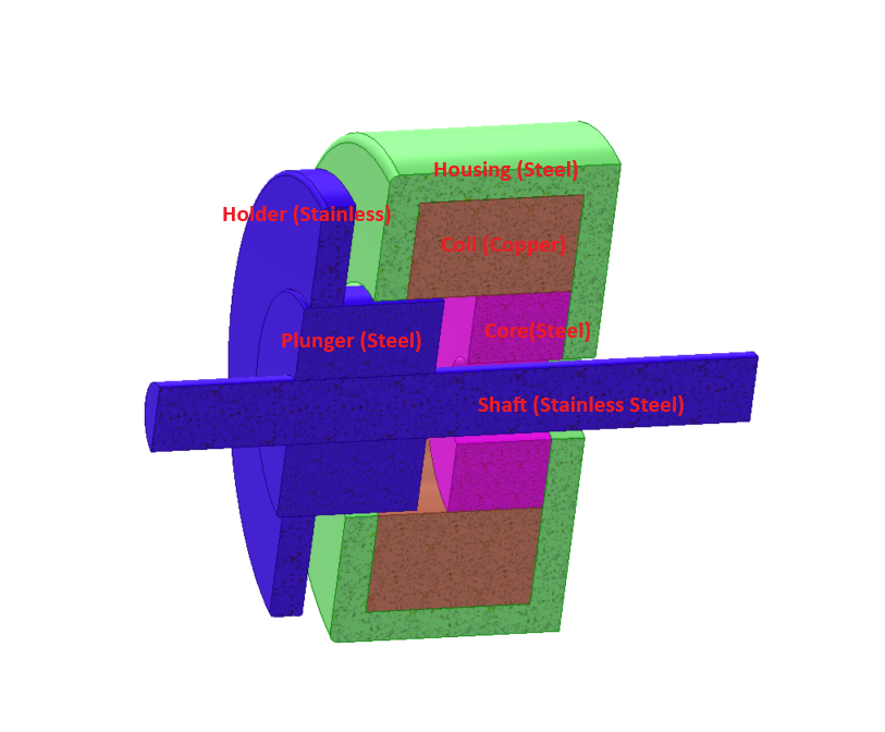
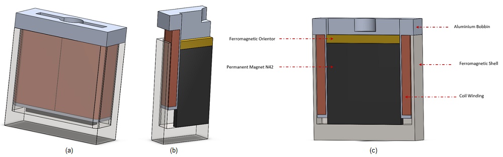
In this article, we analyze a voice coil actuator [1] using EMS. Simulations leverage optimized parameters [1] for transient magnetic studies to compute current under various DC voltage excitations. Results are compared to experimental data [1]. Additionally, we conduct electrothermal analysis with EMS to study temperature evolution. Figures 1a), 1b), and 1c) provide views of the device, featuring a stranded copper coil with 760 turns, moving within an air gap between a ferromagnetic shell and a stationary neodymium magnet. Soft iron components enhance permeability, with a flux oriented guiding the field and a bobbin supporting the coil.
Simulation and Results
Transient Simulation using EMS – Current and force calculation for different voltages
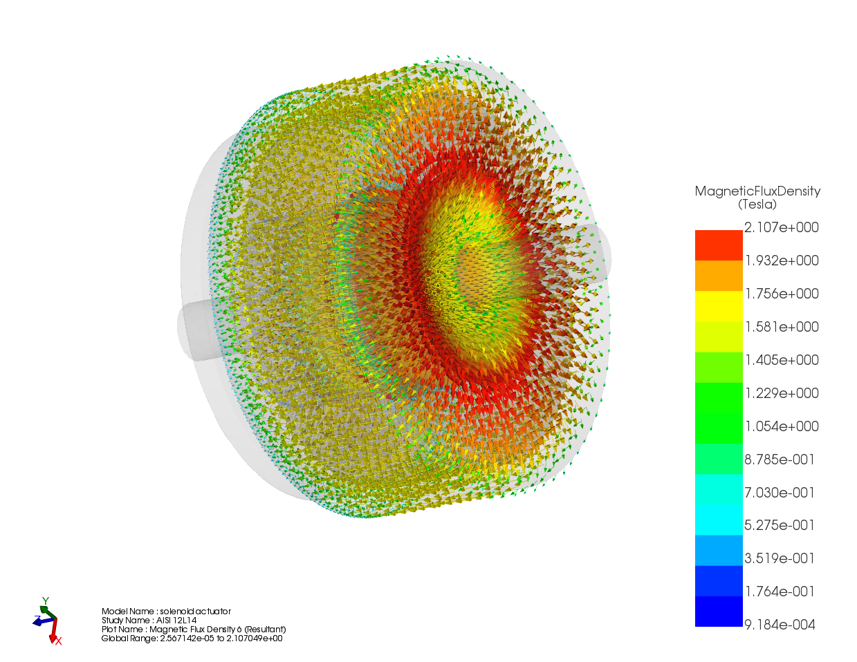
In this section, electromagnetic simulation is conducted using the Transient module of EMS. The coil is supplied with a range of DC voltages, and magnetic fields, current, and Lorentz force are computed. Figure 2 illustrates the magnetic flux density at the point of steady-state attainment.
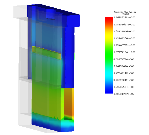
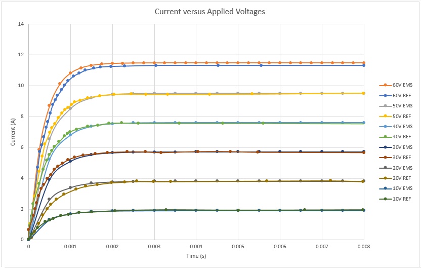
Figure 3 illustrates the calculated current response to various applied voltage rates, demonstrating steady-state attainment within 2ms. This insight can enhance system time response. Computed currents reach 2A and 11A with 10V and 60V applied to the stranded coil, respectively.
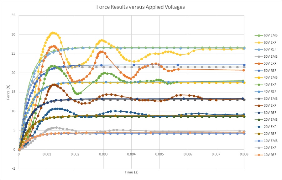
In Figure 4, multiple force plots at a static position (12mm) are presented. Experimental test results exhibit minor oscillations before reaching a steady state. A force of 4.5N is achieved with a 10V DC voltage, while it rises to 26N with a 60V application. Increased voltage correlates with higher force output.
Electrothermal Analysis – Winding loss and temperature calculation of the voice coil actuator
This analysis focuses on electromagnetic losses and the resultant temperature rise in the voice coil actuator. With the neglect of eddy current effects, copper losses (winding losses) predominate. According to Joule's law, current flowing through the winding conductors generates heat, known as Joule heat, causing the temperature of the voice actuator to rise in direct proportion to the applied voltage.
Transient electrothermal analysis, conducted using EMS, computes winding losses and temperature evolution over time for a static coil position. EMS facilitates thermal coupling analysis seamlessly, without requiring data export/import. The electromagnetic time constant is significantly shorter compared to the thermal time constant, resulting in a rapid attainment of an electromagnetic steady state, while the thermal analysis requires a longer duration to reach a steady state. Thus, employing different simulation end times and time step sizes accelerates the analysis.
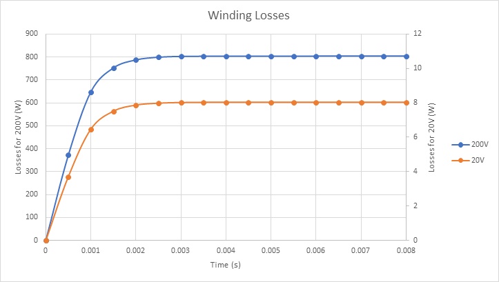
In Figure 5, winding loss results are presented for two voltage scenarios. Copper losses in the voice coil amount to approximately 800W and 8W when 200V and 20V DC voltages are respectively applied.
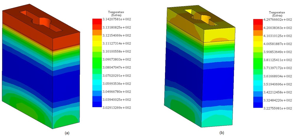
Figures 6a) and 6b) depict the final temperature of the voice coil actuator for 20V and 200V, respectively. Generated within the coil due to copper losses, the temperature then propagates throughout the system via conduction.
In the case of 20V, the temperature peaks at 314 K after 60s, while with 200V, it rises from 300 K ambient temperature to 429 K within 5 seconds, as seen in Figure 7. This confirms the coil as the primary heat source.
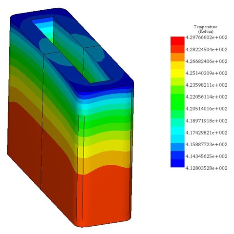
Figure 8 illustrates the temperature evolution for the entire system.
Conclusion
This application note investigates the performance of a voice coil actuator using EMS for transient magnetic and electrothermal analyses. The actuator, featuring a copper coil and neodymium magnet, shows a direct correlation between applied voltage and force output, with currents reaching up to 11A under 60V, generating forces up to 26N. These findings affirm the actuator’s quick response and high force capability, essential for precision applications. The electrothermal analysis reveals that temperature rises significantly with higher voltages, peaking at 429 K under a 200V application within seconds due to copper losses. This temperature increase underscores the actuator's efficient energy conversion into mechanical force and heat. The study validates the actuator's design through simulation results closely matching experimental data, highlighting its suitability in applications demanding rapid and controlled motion.
References
[1]: Vahid Mashatan. Design and Development of an Actuation System for the Synchronized Segmentally Interchanging Pulley Transmission System (SSIPTS). Department of Mechanical and Industrial Engineering University of Toronto 2013