Introduction
This application note analyzes a voltage-driven DC solenoid using coupled magnetostatic and steady-state thermal simulation. It shows how temperature-dependent copper resistance reduces current, magnetic flux density, and plunger force at steady state. The results explain why force estimates based on fixed current or cold-coil assumptions are inaccurate for voltage-driven solenoids.
Problem Statement
Solenoids are frequently analyzed assuming a fixed current. In real applications, many solenoids are powered by a fixed voltage source. Under voltage excitation, coil current is not prescribed; it depends on the electrical resistance of the winding. Because copper resistance increases with temperature, electrical, magnetic, and thermal effects are inherently coupled.
If this coupling is ignored, simulations can: Overestimate steady-state current, overpredict magnetic flux density, overpredict plunger force, and underestimate operating temperature.
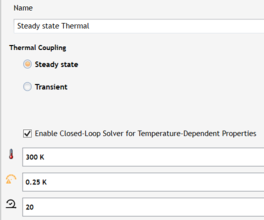
This note demonstrates these effects using a closed-loop electro-thermal simulation. The closed-loop parameters are shown in Figure 1.
Model Overview
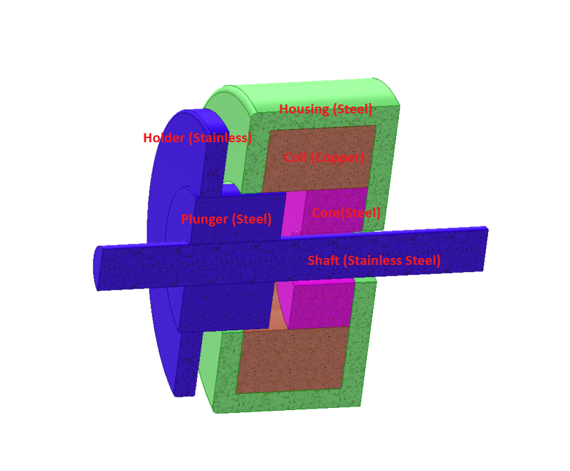
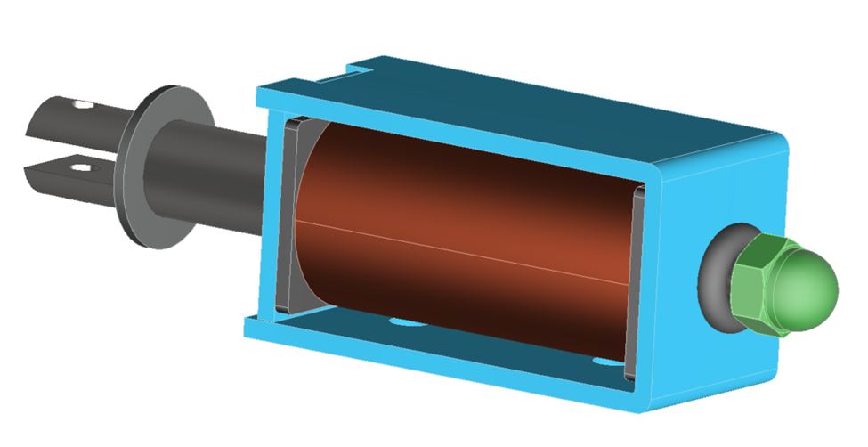
The model consists of a wound copper coil, a steel yoke, and a movable steel plunger. The geometry represents a compact DC solenoid used for linear actuation, as shown in Figure 2.
- Coil material: Copper with temperature-dependent conductivity
- Core and plunger material: Electrical steel M310-50A with nonlinear B–H behavior
- Surrounding region: Air
All simulations are three-dimensional and solved using CAD-integrated finite element analysis.
Electric Excitation
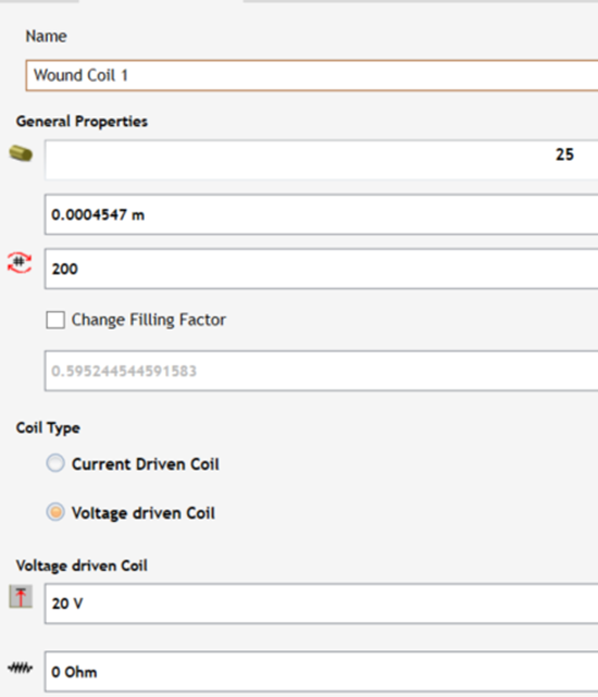
The coil is modeled as a voltage-driven wound coil, as shown in Figure 3.
Applied voltage: 20 V DC
External series resistance: 0 Ω
Number of turns = 200.
AWG = 25.
The solver computes coil current from:
I = V / R(T)
where R(T) is the temperature-dependent winding resistance.
Temperature-Dependent Conductivity of Copper
Copper conductivity is modeled as:
σ(T) = σ₀ / [ 1 + α (T − T₀) ]
with: - σ₀ = 5.7 × 10⁷ S/m at T₀ = 300 K - α = 0.03 K⁻¹
This model captures the linear increase of copper resistivity with temperature over the operating range of the solenoid.
Example values
| Temperature (K) | Temperature (°C) | Conductivity σ(T) (S/m) |
| 300 | 27 | 5.70 x 10⁷ |
| 320 | 47 | 4.38 x 10⁷ |
| 340 | 67 | 3.55 x 10⁷ |
| 360 | 87 | 2.97 x 10⁷ |
As temperature rises, conductivity decreases, increasing resistance and reducing current under voltage excitation.
Magnetic Material Model
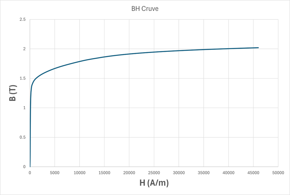
The yoke and plunger are modeled using non-oriented electrical steel M310-50A. A nonlinear B–H curve, shown in Figure 4, is used to capture saturation effects in regions of high flux density, particularly near air gaps and corners. Using a nonlinear steel model is required to correctly predict how reduced excitation shifts the operating point on the B–H curve and affects force.
Magnetostatic Results
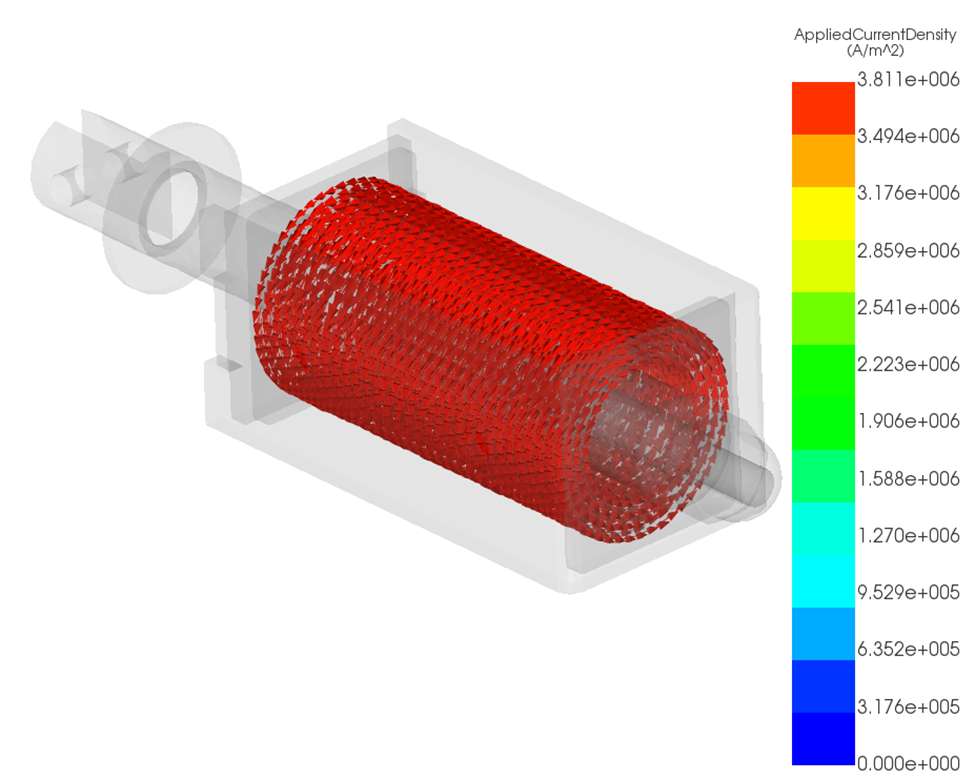
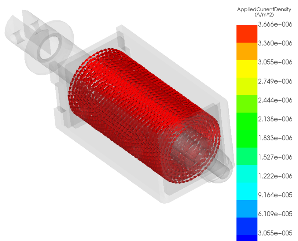
Current Density
When temperature dependence is disabled, current density remains artificially high because resistance is fixed, as shown in Figure 5. When temperature dependence is enabled, increased copper temperature raises resistance and reduces current density throughout the coil, as shown in Figure 6.
This behavior cannot be reproduced using current-driven excitation.
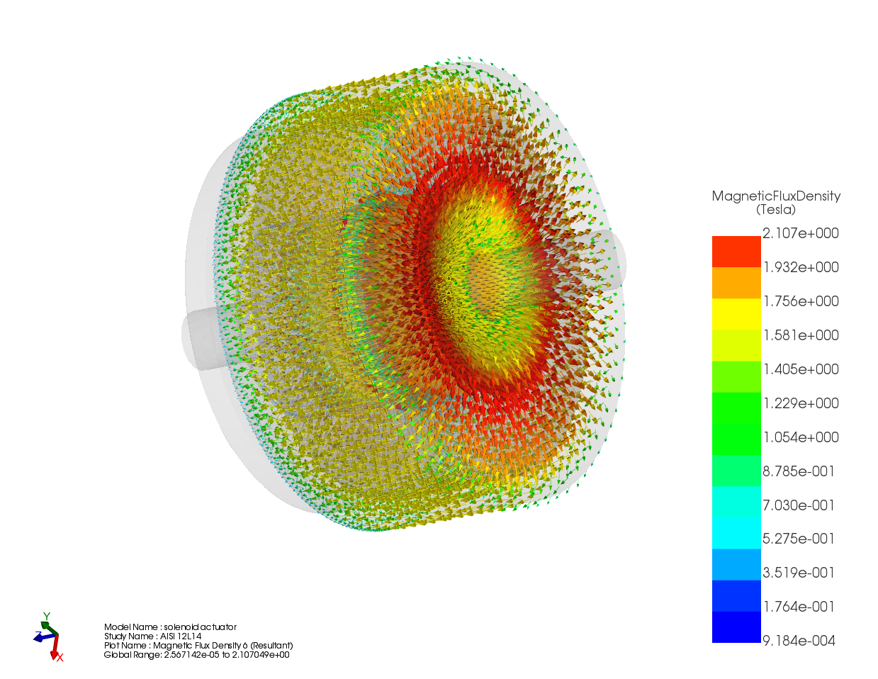
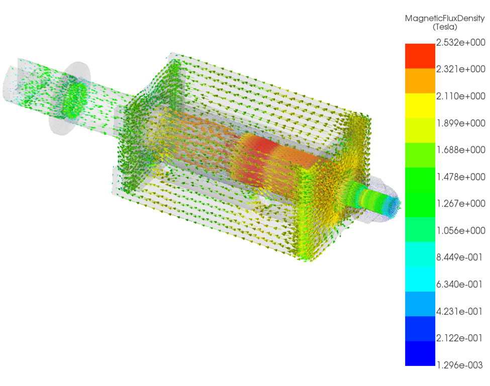
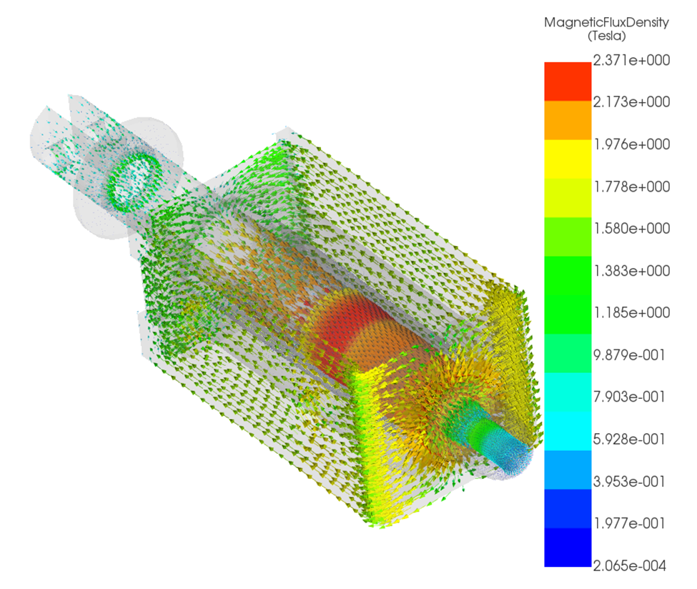
Magnetic Flux Density
Reduced current leads to lower magnetic flux density in the plunger and yoke. While the spatial distribution of flux remains similar, the magnitude decreases when thermal feedback is included. This directly affects force generation. Results are shown in Figure 7 and 8.
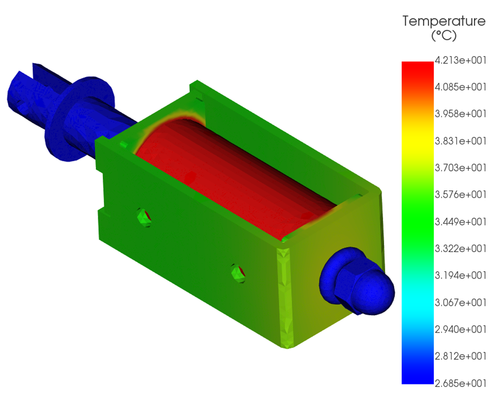
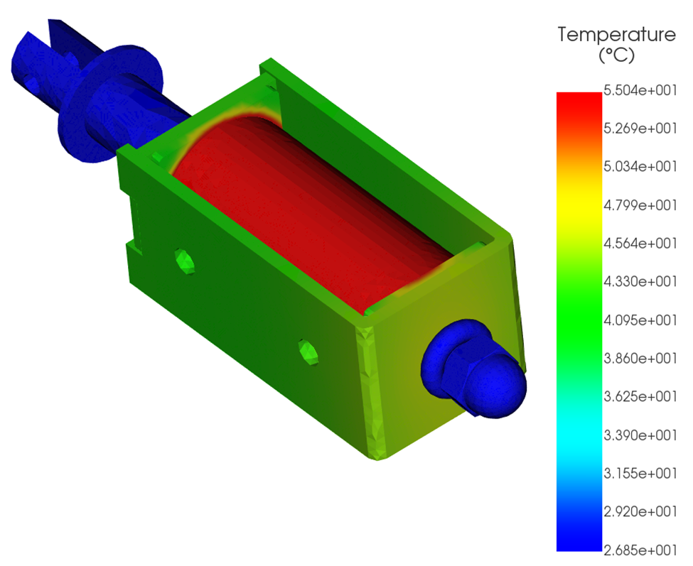
Thermal Results
A steady-state thermal analysis is coupled to the magnetostatic solution:
- Heat source: Joule losses computed from J²/σ(T)
- Ambient temperature: 300 K
- Natural convection applied to external surfaces
The solution converges when electrical, magnetic, and thermal fields are consistent. Temperature distribution for both cases are shown in Figures 9 and 10.
Effect on Plunger Force
The impact of temperature-dependent resistance is quantified by comparing two studies.
| Case | Ampere-turn (A·turn) | Plunger Force (N) | Resistance (Ω) |
| Temperature-independent resistance | 5684.035 | 10.637 | 0.703 |
| Temperature-dependent resistance | 3080.109 | 6.242 | 1.298 |
Including temperature dependence:
- Resistance increases by ~85%
- Ampere-turns decrease by ~46%
- Plunger force decreases by ~41%
The reduction in force occurs even though geometry and materials are unchanged. It is caused solely by electro-thermal feedback under voltage excitation.
Design Implications
For voltage-driven solenoids:
- Force should be evaluated at steady-state temperature, not cold conditions
- Current-driven simulations are not representative of real operation
- Ignoring temperature dependence leads to optimistic force predictions.
Coupled electro-thermal analysis is required for realistic assessment of continuous-duty performance.
Conclusion
Voltage-driven solenoids exhibit strong coupling between electrical resistance, temperature, magnetic excitation, and force. As copper heats up, resistance increases, current decreases, and plunger force drops. Accurate force and temperature prediction requires solving the closed loop of electromagnetic and thermal problems together using temperature-dependent material properties.
All results presented here were obtained using EMWorks EMAG.