Purpose of This Study
This application note examines the electromagnetic operating behavior of a consequent-pole coaxial magnetic gear (CP-CMG) using finite-element simulation. The focus is on magnetic flux modulation, saturation behavior in ferromagnetic components, and torque generation under prescribed rotational motion.
All torque results presented in this study are obtained using motion-enabled finite-element analysis with a prescribed rotational speed of 314 rad/s, while eddy current effects are neglected. Under these assumptions, the solution represents a quasi-static electromagnetic response corresponding to a sequence of magnetostatic field solutions sampled along the rotation trajectory.
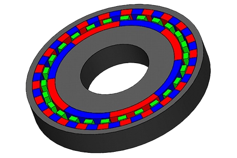
Geometry and Pole Configuration
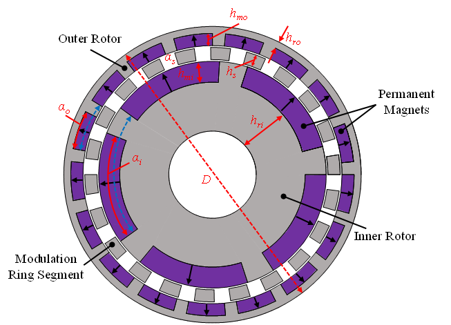
The CP-CMG configuration consists of an inner rotor, a stationary ferromagnetic modulation ring, and an outer rotor. Both rotors employ a consequent-pole topology in which all permanent magnets on a given rotor are magnetized in the same radial direction, while intermediate ferromagnetic segments complete the magnetic circuit. The magnetization direction is uniform within each rotor but opposite between the two rotors: the outer rotor magnets are radially inward magnetized, whereas the inner rotor magnets are radially outward magnetized.
Design Parameters
| Parameter | Value |
| Number of pole-pairs of outer rotor (po) | 17 |
| Number of ferromagnetic pole-pieces (Z) | 22 |
| Number of pole-pairs of inner rotor (pi) | 5 |
| Overall diameter (D) | 170 mm |
| Stack axial length (L) | 45 mm |
| Yoke thickness of outer rotor (hro) | 4 mm |
| Thickness of outer rotor PMs (hmo) | 7 mm |
| Length of outer air-gap (go) | 1 mm |
| Length of inner air-gap (gi) | 1 mm |
| Thickness of ferromagnetic pole-pieces (hs) | 7mm |
| Width ration of ferromagnetic pole pieces (αs) | 0.6 |
| Thickness of inner rotor PMs (hmi) | 12 mm |
| Yoke thickness of inner rotor (hri) | 28 mm |
| PM properties (Br, Hc) | 1.3 T, 995 kA.m-1 |
| Pole-arc coefficient of outer rotor PMs (αo) | 0.75 |
| Pole-arc coefficient of inner rotor PMs (αi) | 0.8 |
The selected pole-pair combination (po = 17, pi = 5, Z = 22) results in a theoretical transmission ratio of 3.4. These parameters also influence flux concentration and saturation behavior in the modulation ring and rotor yokes. The coefficient αo represents the ratio of the magnet pole-arc to the pole-pair pitch on the outer rotor, while αi denotes the same ratio for the inner rotor.
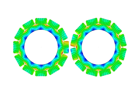
Flux Density in Steel and Permanent Magnets
Figures 2 and 3 show the magnetic flux density distribution in both the steel components and the permanent magnets. High flux density regions are observed at the magnet–steel interfaces and within the ferromagnetic modulation segments, with local values reaching the saturation range of the steel. These saturated regions limit further increases in flux transfer across the air gap and reduce the effective permeance of the magnetic circuit. As a result, part of the magnet flux is locally constrained, contributing to increased harmonic distortion in the air-gap field.
Within the permanent magnets, the flux density remains below the intrinsic demagnetization limit, indicating stable magnet operation under the evaluated condition. The contrast between saturated steel regions and unsaturated magnets confirms that torque capability is limited by steel saturation rather than magnet strength.
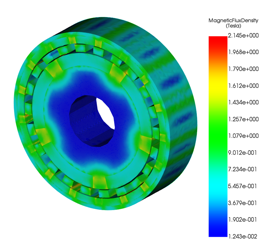
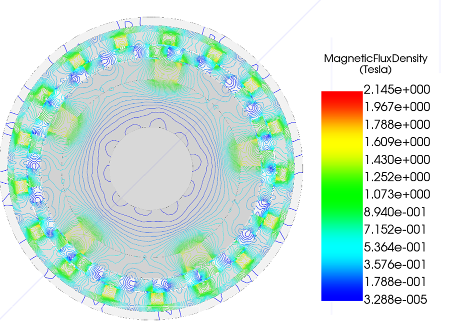
Flux Density Distribution in the Entire Gear
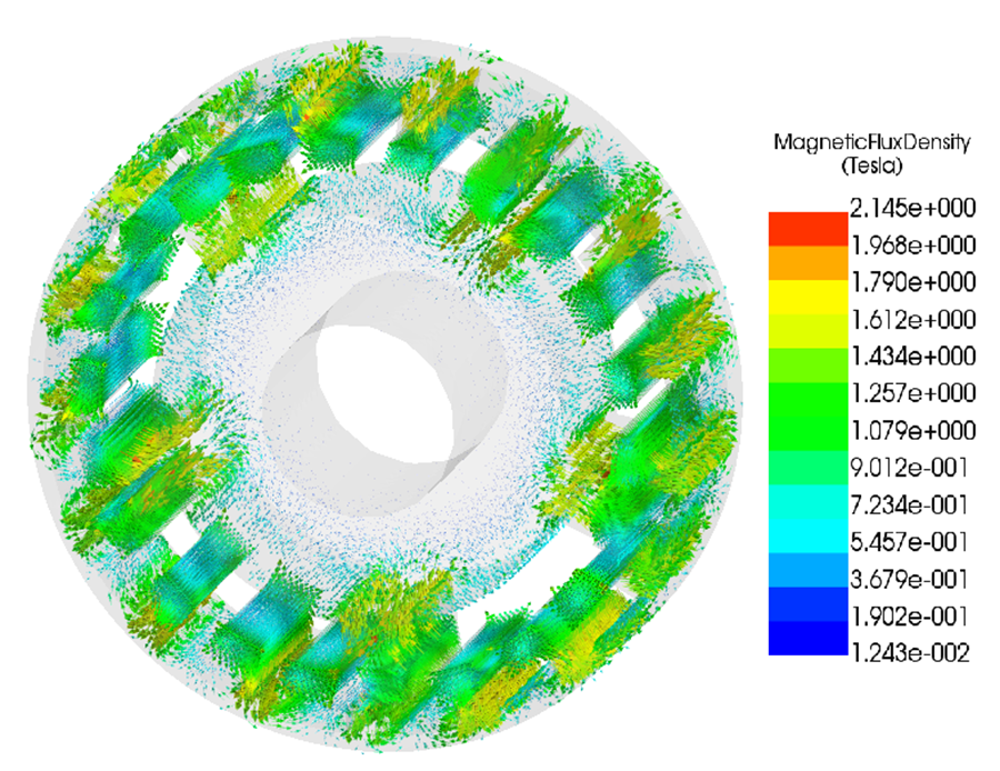
Figures 4 and 5 show section plots of the magnetic flux density across the entire magnetic gear, including magnets, steel components, and air regions.
The flux density distribution confirms that magnetic flux is predominantly guided through the modulation segments and rotor back irons, with strong spatial modulation imposed by the ferromagnetic pole pieces. High-flux regions are concentrated near the magnet–steel interfaces and within the modulation ring, where local saturation is evident. These regions define the primary flux transfer paths between the inner and outer rotors.
The interior rotor core exhibits comparatively low flux density, indicating limited participation in torque transmission and confirming effective confinement of the active magnetic field to the air gap and modulation region. The asymmetric and non-uniform flux distribution reflects the presence of multiple space harmonics required for torque transmission.
Overall, the section plots provide a global view of the magnetic circuit, showing that torque capability is governed by harmonic flux routing through the modulation ring and is limited by localized saturation in the steel components.
Saturation Assessment
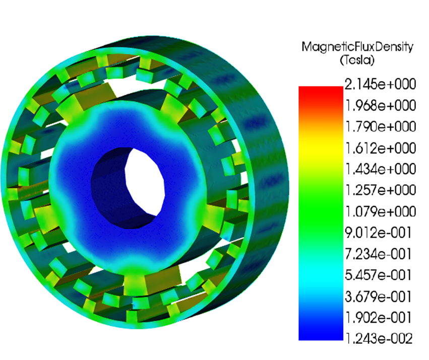
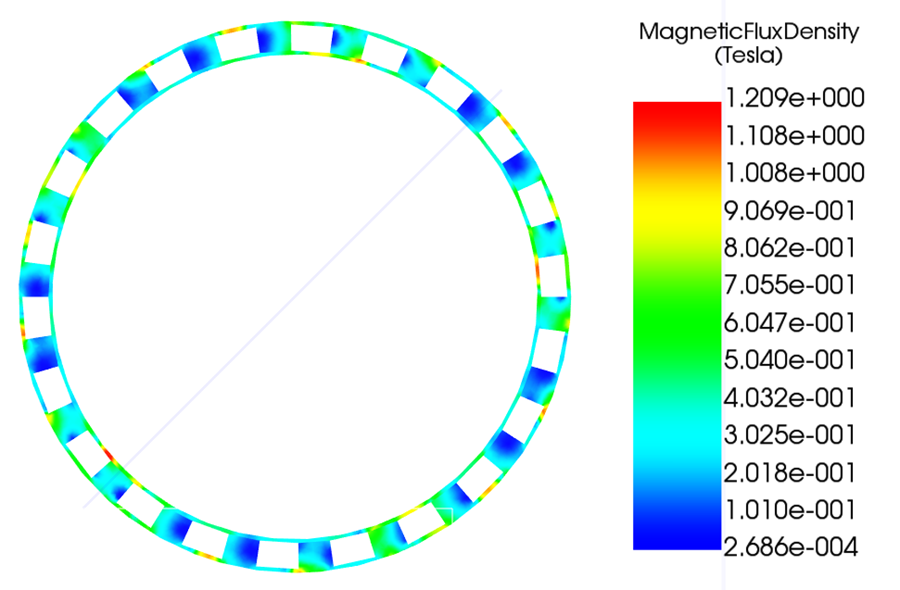
Figure 6: Magnetic flux density in steel components only, fringe plot.
Figures 6 and 7 show the magnetic flux density distribution in the steel components only, including the inner rotor core, outer rotor back iron, and the ferromagnetic modulation ring.
Localized regions in the modulation segments and rotor back irons reach flux density levels close to or above magnetic saturation. These saturated zones occur primarily at magnet–steel interfaces and at the tips of the modulation segments, where flux is concentrated and redirected across the air gap. Saturation limits further increase in local flux density and alters the effective permeance of the magnetic circuit.
As a result, torque transmission becomes increasingly constrained by the saturation behavior of the steel rather than by the available magnet flux. The presence of saturation also increases harmonic distortion in the air-gap field, which can affect torque ripple and pull-out torque.
These results indicate that steel saturation is an active limiting factor in the current design and should be considered when optimizing modulation segment geometry, back-iron thickness, or material grade.
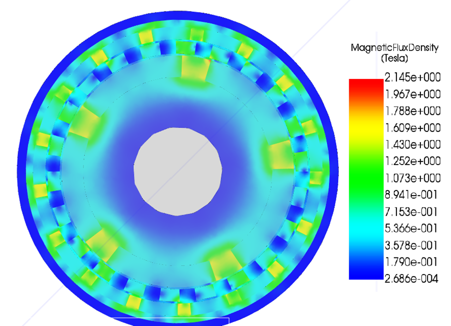
Air-Gap Flux Density and Harmonic Content
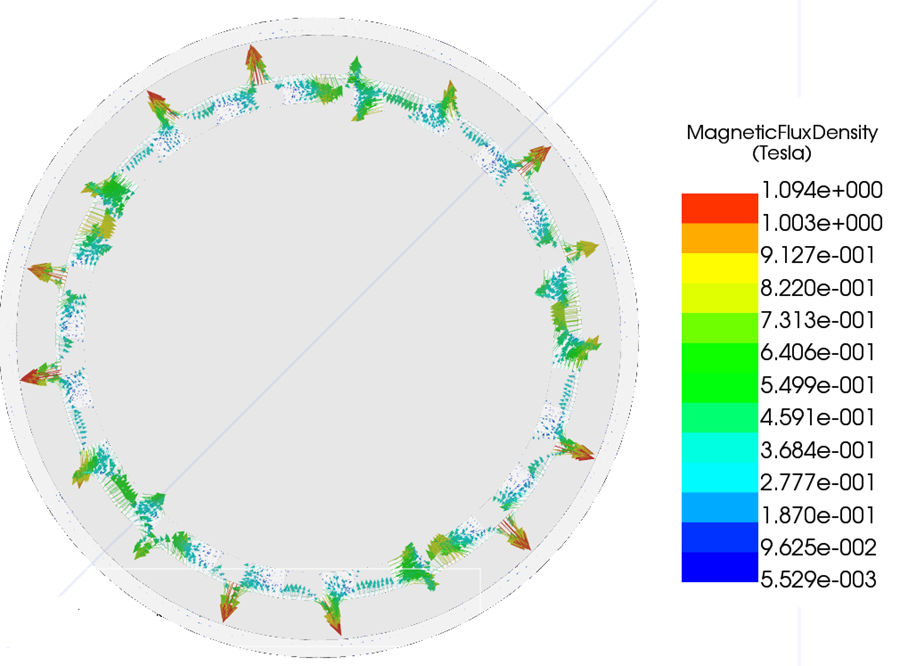
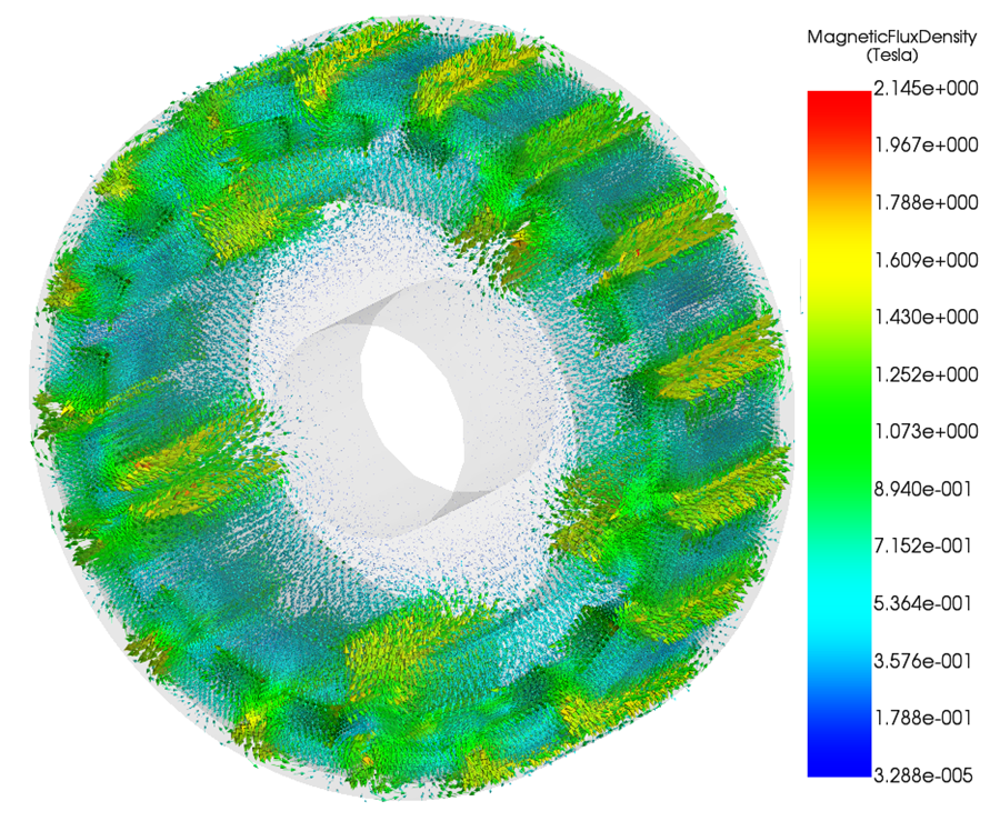
Figures 8 and 9 show the magnetic flux density in the air gap, presented as a magnitude (fringe) plot and a vector plot.
The fringe plot in Figure 8 shows a clearly modulated air-gap flux density with periodic high- and low-field regions. This spatial modulation indicates the presence of multiple space harmonics generated by the interaction between the consequent-pole rotors and the ferromagnetic modulation ring. The peak air-gap flux density remains below saturation while providing sufficient field strength for torque transmission.
The vector plot in Figure 9 shows periodic variations in both magnitude and direction of the air-gap field. These variations confirm the existence of traveling harmonic components in the circumferential direction. The resulting non-uniform Maxwell stress distribution is responsible for torque transmission between the rotors.
Together, these plots confirm that torque is produced through harmonic coupling in the air gap, consistent with the operating principle of coaxial magnetic gears.
Quasi-Static Torque Waveforms under Prescribed Rotation
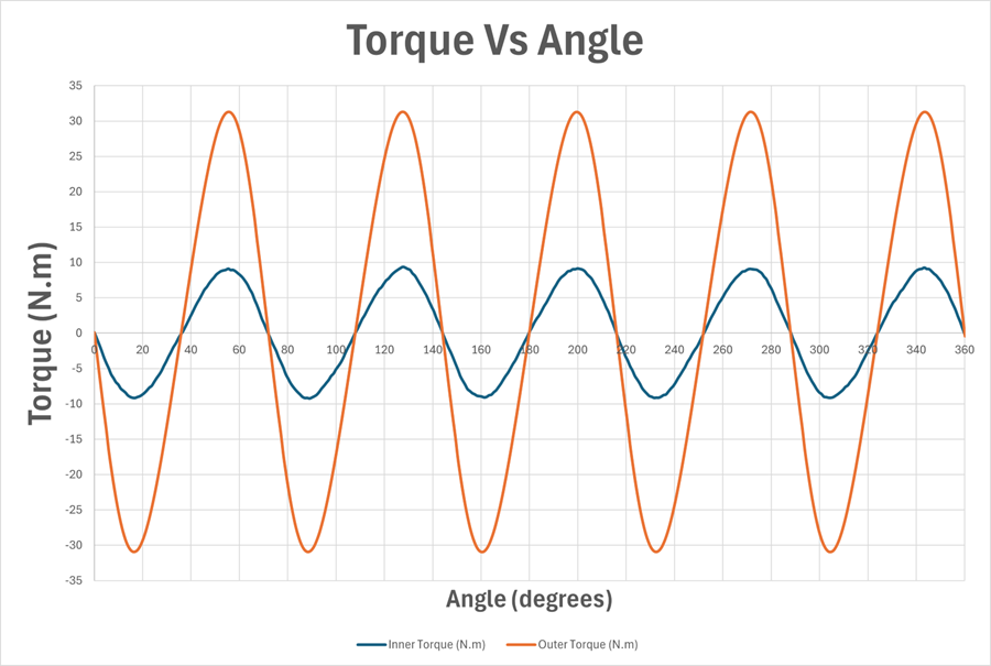
Figure 10 shows the quasi-static torque as a function of the relative angular displacement between the inner and outer rotors, with the modulation ring fixed. The results are obtained using a transient magnetic formulation with eddy currents neglected, such that each angular position corresponds to a quasi-static magnetic equilibrium.
Both inner and outer torque waveforms are highly sinusoidal over the full 0–360° sweep, with consistent zero crossings, extrema, and symmetry. This indicates that torque transmission is dominated by fundamental space harmonic, with very low harmonic distortion. The maximum quasi-static torque reaches approximately 9.2–9.3 N·m on the inner rotor and 31.2–31.3 N·m on the outer rotor, and these values repeat consistently over each electrical period.
The torque ratio remains nearly constant at ≈ 3.35–3.4 across the entire angular range. The inner and outer torques are phase-locked with a fixed phase offset, confirming efficient torque transmission from the inner rotor to the outer rotor with no evidence of slip or nonlinear coupling.
Overall, the results confirm operation in a well-synchronized harmonic coupling regime, where torque amplification is governed by the magnetic gear ratio and ultimately limited by magnetic saturation in the steel components.
Static Pull-Out Torque

The pull-out torque is evaluated using a magnetostatic torque–angle sweep in which the modulation ring and outer rotor are held fixed, while the inner rotor is incrementally displaced in angular position. Eddy current effects are neglected, and each angular position is solved as an independent magnetostatic equilibrium, as shown in Figure 11.
At each relative angular displacement ∆θ , the electromagnetic torques acting on the inner and outer rotors, Ti(Δθ) and To(Δθ) , are computed. A conservative measure of the transmitted torque is defined as
$$ T_{\text{trans}}(\Delta \theta) = \min\!\left( \left|T_i(\Delta \theta)\right|, \left|T_o(\Delta \theta)\right| \right) $$
which represents the torque level that can be simultaneously supported by both rotors.
Plotting $$ \Delta\theta_{\text{pullout}} \approx 128^\circ $$ as a function of ∆θ yields a periodic torque–angle characteristic reflecting the magnetic symmetry of the gear. The pull-out torque is defined as the maximum value of this curve,
$$ T_{\text{pullout}} = \max_{\Delta\theta} \; T_{\text{trans}}(\Delta\theta) $$
and corresponds to the loss of stable magnetic phase locking.
For the configuration studied here, the pull-out torque is found to be
$$ T_{\text{pullout}} \approx 9.4\,\mathrm{N\cdot m} $$
occurring at a relative angular displacement of
$$ \Delta\theta_{\text{pullout}} \approx 128^\circ $$
Beyond this point, the electromagnetic restoring torque decreases with increasing displacement, indicating unstable equilibrium and loss of synchronism. The pull-out torque therefore defines the upper bound for stable synchronous operation and provides a quantitative stability limit for the CP-CMG design.
Design Takeaways
- Pull-out torque defines the synchronizing limit and must exceed operating torque to maintain phase lock.
- The quasi-static torque waveform is governed by electromagnetic harmonics, not inertia or dynamic effects.
- Steel saturation in the modulation ring and rotor yokes is the primary torque-limiting factor in CP designs.
- Air-gap flux density harmonics provide a direct diagnostic for torque capability and waveform quality.
- Eddy currents modify damping but do not change the fundamental torque transmission mechanism.
Conclusions
This study demonstrates how finite-element simulation can be used to analyze flux modulation, magnetic saturation, and torque transmission in consequent-pole coaxial magnetic gears. By combining torque–angle sweeps with quasi-static transient motion analyses (with eddy currents neglected), both synchronizing capability and intrinsic torque behavior are clearly characterized. The results show that torque transmission is governed by harmonic coupling and limited by steel saturation, providing clear guidance for CP-CMG design optimization.
All simulations and results presented in this work were obtained using EMWorks EMAG.