Eddy Current Braking
Eddy current brakes harness electromagnetic induction to create braking forces through eddy currents in conductors. They are categorized into:
1. Electrical Excitation ECB: Adjustable braking via electromagnets, enhanced by permanent magnets for efficiency.
2. Permanent Magnet ECB: No external power needed, fixed force, with concerns of magnet corrosion and heat tolerance.
3. Hybrid Excitation ECB: Merges the first two types for adjustable, efficient braking with minimal loss.
CAD Model
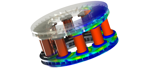
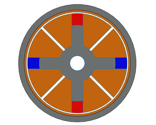
This analysis introduces a Radial Flux Hybrid Excitation ECB system, illustrated in Figure 1. It features a stationary section with two pairs of radially polarized permanent magnets and copper windings within the inner back iron, and a moving section with a conductive layer on the outer cylindrical back iron, separated by a 1mm air gap. Motion analysis is conducted with EMWorks2D using a Transient Magnetic study, with material assignments for each component detailed in Table 1.
| BS Component | Material |
| Inner and Outer Back Iron | AISI 1010 Steel |
| Windings | Copper |
| Conductive Layer | Copper |
| PMs | N4212 |
Electrical Excitation ECB Mode
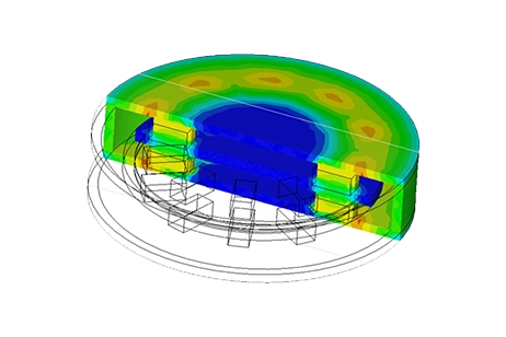
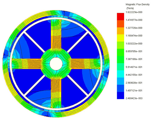
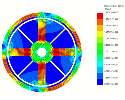
In this section of the analysis, the electrical excitation mode is engaged by powering all windings with a current density of 14 A/mm^2 and substituting permanent magnets with iron. A test at 3000 rpm generates the magnetic flux mapping depicted in Figure 2, highlighting a peak flux concentration in the primary core reaching 1.63 Tesla at a 30 ms time step.
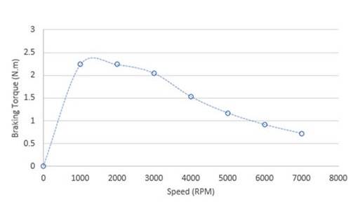
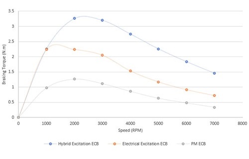
The second figure illustrates the relationship between maximum braking torque and various speeds after 30 ms, clearly showing that the peak braking torque occurs at approximately 1500 rpm.
Permanent Magnet ECB Mode
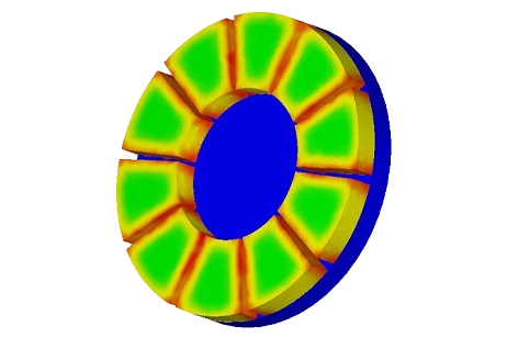
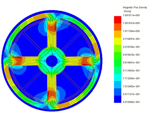
In this part of the analysis, the PM-ECB mode is initiated by removing all windings and retaining the permanent magnets. Conducting a test at 3000 rpm yields the magnetic flux mapping in Figure 3, where the maximum flux is focused through the permanent magnets, reaching 1.09 Tesla at a 30 ms time step.
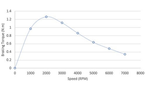
The subsequent 2D plot displays the maximum braking torque against various speeds after 30 ms, revealing a peak torque of 1.27 N.m at 2000 rpm.
Hybrid Excitation ECB Mode
In the third part, the Hybrid excitation mode is examined for the ECB system design, maintaining both windings and permanent magnets. Rotating the outer core, along with the attached conductive layer, at 3000 rpm, the simulation presents the flux mapping at a 30 ms time step.
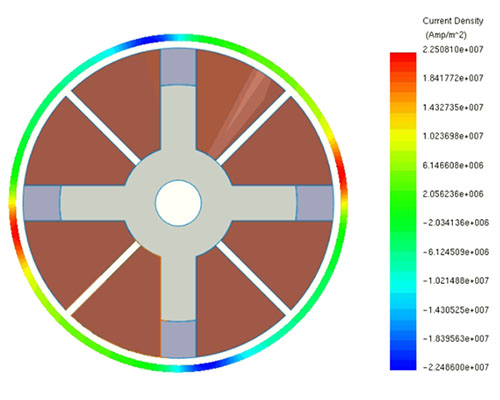
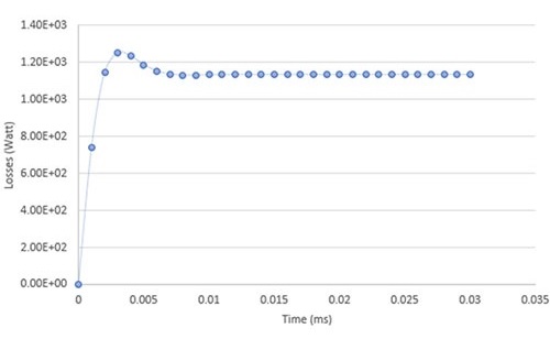
At the same speed, the distribution of Eddy Current density across the conductor layer is plotted, showing high induced currents reaching 2.25 E+7 A/mm^2. The eddy currents lead to induced solid losses, with the second figure illustrating their variation over time, peaking at around 1150W.
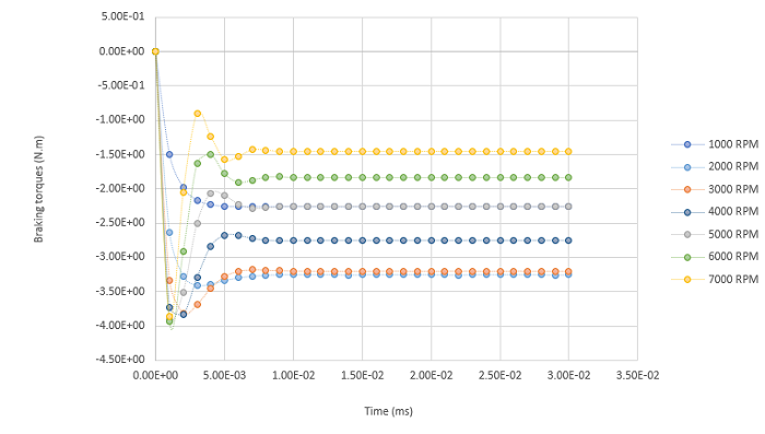
The subsequent 2D plot compares the braking torque against speed for the Hybrid Excitation mode with other modes, highlighting that the highest braking torque values are achieved with this combined ECB system design. Another 2D plot demonstrates the progression of braking torque over time for various speeds, indicating that the torque stabilizes after approximately 10 ms of rotation in all speed scenarios.
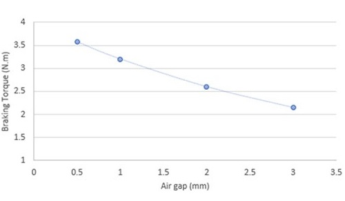
The final analysis explores the impact of air gap size between the stationary and rotary parts on braking torque, using parametric analysis in EMWorks2D. At a constant speed of 3000 rpm, the figure illustrates that decreasing the air gap leads to a direct increase in braking torque.
Conclusion
The application note examines a Radial Flux Hybrid Excitation Eddy Current Brake (ECB) system across three operational modes: Electrical Excitation, Permanent Magnet, and Hybrid Excitation. Using EMWorks2D, it analyzes braking torque at various speeds and conditions. Electrical Excitation mode yields a peak flux of 1.63 Tesla and optimal torque at 1500 rpm. Permanent Magnet mode focuses flux through magnets, with peak torque at 2000 rpm. Hybrid Excitation mode combines windings and magnets, generating the highest torque but with notable eddy current losses. Comparatively, Hybrid Excitation offers superior torque performance. A parametric study highlights the system's sensitivity to air gap size, with smaller gaps correlating to increased torque. This research underscores Hybrid Excitation ECB's potential for efficient, adjustable braking, crucial for diverse applications. It emphasizes precise design and mode selection for optimal performance, offering valuable insights into magnetic braking technology advancement.
References
[1]. Yazdanpanah, Reza. "Design and Analysis of Radial-Flux Hybrid Excitation Eddy Current Brake." 2019 10th International Power Electronics, Drive Systems and Technologies Conference (PEDSTC). IEEE, 2019.