Dielectric Resonator Antennas
The telecommunications landscape is rapidly evolving, particularly in wireless systems, revolutionizing communication and business networks. As cellular technologies advance to 5G, emphasis is on enhancing bandwidth for long-distance communication, crucially reliant on efficient antenna devices. However, conventional microstrip patches and Vivaldi antennas face limitations such as narrow bandwidth and high conductor loss. To address these challenges, Dielectric Resonator Antenna (DRA) technology offers promising solutions, boasting advantages like lightweight, low cost, and wider bandwidth. This study explores HFWorks' capabilities in simulating the electromagnetic and thermal behavior of rectangular DRAs tailored for 5G applications, analyzing fundamental and high-order modes. Experimental prototypes referenced in [1] are provided below.
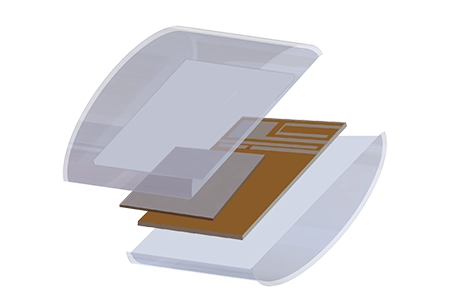
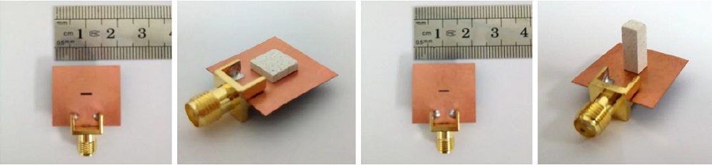 Figure1 - The fabricated DRA prototypes used by the Ref [1]
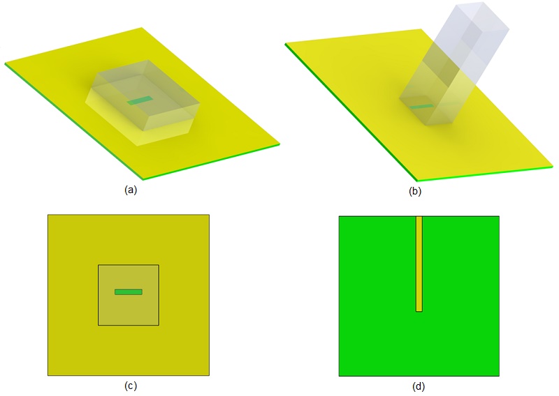
CAD Model
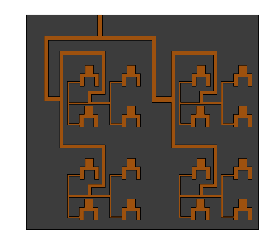
The Dielectric Resonator Antenna (DRA) comprises essential components: a ceramic radiator, a dielectric substrate, conducting ground, and a metallic 50? feed line. These DRAs operate within the frequency range of [13 GHz-17 GHz], with specific dimensions outlined in Table 1 for each mode.
| Part | Dimension (mm) | |||
| Substrate | Height:20 | Width:20 | Length:0.25 | |
| Dielectric resonator -Fundamental mode | Height:7.5 | Width:7.5 | Length:1.8 | |
| Dielectric resonator -High-order mode | Height:4 | Width:4 | Length:11.5 | |
| Feed line-Fundamental mode | Width: 0.79 | Length:11.92 | ||
| Feed line-High order mode | Width: 0.73 | Length:11.92 | ||
| Aperture slot-Fundamental mode | Width: 0.65 | Length:3.34 | ||
| Aperture slot-High order mode | Width:0.4 | Length:3.34 | ||
| Slot position from feed line-Fundamental mode | 2 | |||
| Slot position from feed line order mode | 1.4 | |||
| Material | Relative permittivity | Dielectric loss tangent | Electrical conductivity (S/m) |
Thermal conductivity (W/m. K) |
| Air | 1.00058986 | 0 | 0 | 0.024 |
| Arlon AR1000 | 10 | 0.0035 | 0 | 0.645 |
| Epoxy FR4 | 2.2 | 0.001 | 0 | 0.36 |
Electromagnetic boundary conditions
Wave Port: Applied to the substrate input face adjacent to the feeding line.
Perfect Electric Conductor (PEC): Applied to the ground and feed line faces.
Radiation: Applied to the outer air box faces for simulating radiation effects.
Study 1: Excitation of fundamental mode
The initial analysis explores the Fundamental excited mode of the first DRA topology within the frequency range of 13 GHz to 17 GHz. The antenna simulation provides the following results:
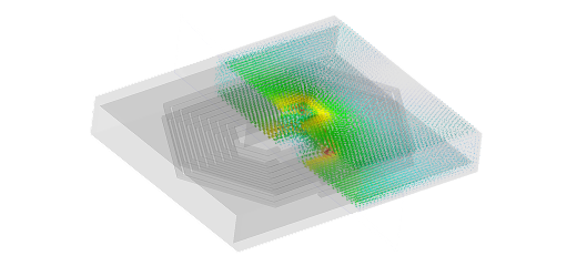
An animated plot illustrates the electric field distribution inside the dielectric box across different phases, with an excitation power of 1 Watt.
The return loss 2D plot is superposed to the measurement results mentioned by the ref [1] to show a good agreement between them. The measured bandwidth for achieved 1.7GHz.
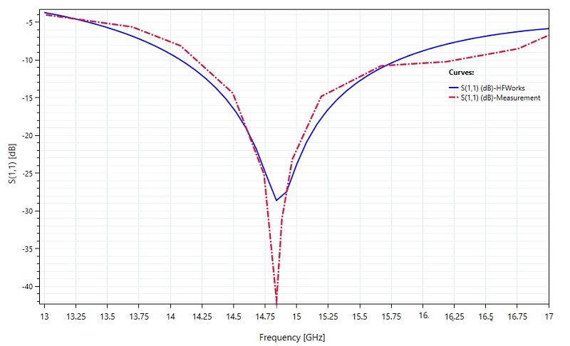
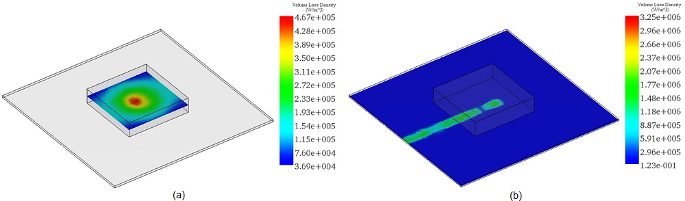
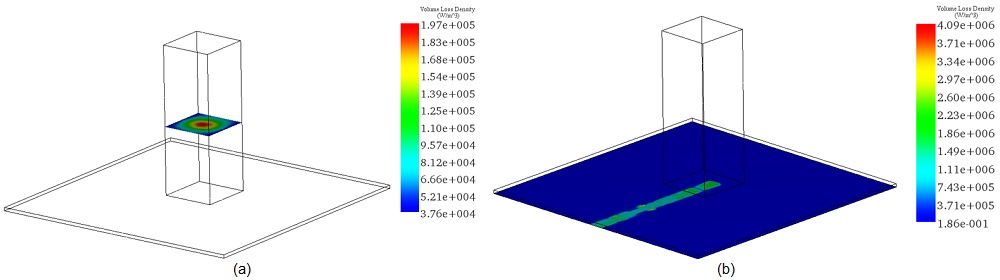
Given the emphasis on dielectric resonators in the new DRA topologies, analyzing losses is crucial. Mapping volume losses for the DRA at 15 GHz reveals significant dielectric losses, particularly evident at lower power levels.
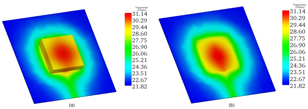
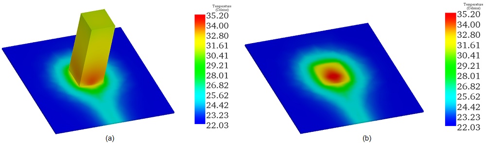
Conducting a steady-state thermal analysis coupled with antenna study enabled the prediction of temperature profiles for the examined DRA example. Applying a convection boundary condition to the surrounding air yielded temperature distributions for the 15 GHz frequency, reaching a maximum of 31°C across the resonator box.
Study 2: Excitation of High-order Mode
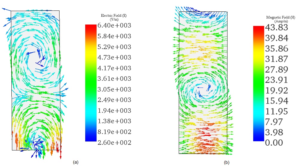
Exploring the high-order radiation mode for the second DRA topology involves a similar frequency range and electromagnetic boundary conditions as in the first study. The sectional vector plot results depict the distribution of electric and magnetic fields across the resonator box.
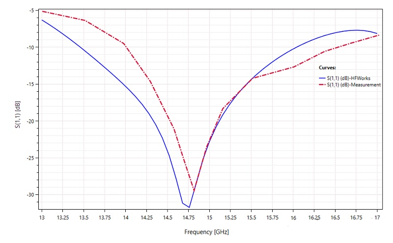
The 2D plot below showcases the return loss of the higher order DRA, comparing simulation results to measurements. With an increased height of the rectangular dielectric resonator, this second design exhibits improved bandwidth compared to the fundamental mode design.
The simulated gain results, compared to both experimental and reference simulation results, are summarized in the table below. It demonstrates a favorable agreement between HFWorks and experimentally measured data.
| Results | Measurement | Simulation-HFWorks | Simulation-Ref [1] |
| Gain (dB) | 9.76 | 9.65 | 9.95 |
Ultimately, a thermal coupling analysis is conducted under the same thermal boundary conditions as the first study. With an excitation power set to 1 watts, the steady-state temperature of the model reaches 35°C, primarily attributed to dielectric losses induced by the materials employed.
Conclusion
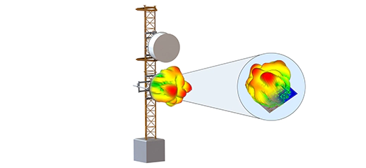
This application note delves into the potential of Dielectric Resonator Antennas (DRAs) for 5G wireless systems, offering a compelling alternative to traditional antenna solutions like microstrip patches and Vivaldi antennas. With their inherent advantages of wider bandwidth, lower cost, and reduced weight, DRAs represent a significant advancement in telecommunications technology. The study employs HFWorks to simulate the electromagnetic and thermal behavior of rectangular DRAs, focusing on both fundamental and high-order modes suitable for the 5G frequency range of 13 GHz to 17 GHz. The simulations confirm the DRAs' enhanced performance capabilities, including superior bandwidth and gain, alongside efficient thermal management. The fundamental mode DRA exhibits a return loss bandwidth of 1.7 GHz, while the high-order mode DRA shows improved bandwidth and gain, demonstrating the technology's adaptability to various 5G applications. Thermal analyses predict maximum temperatures of 31°C and 35°C for the fundamental and high-order mode DRAs, respectively, underlining the designs' thermal efficiency.
References
[1]- Shahadan, Nor Hidayu, et al. "Higher-order mode rectangular dielectric resonator antenna for 5G applications." Indonesian Journal of Electrical Engineering and Computer Science 5.3 (2017): 584-592.