An RF Power Divider
RF and microwave systems rely on precise power distribution networks using dividers to split input signals and combiners to merge RF inputs. These are crucial in high-power applications like accelerators and radars, requiring accurate power splitting and low losses.
Waveguide-based structures are commonly used for multi-port dividers/combiners due to their high power handling and low loss at high frequencies. The Folded H-plane tee junction is a three-port divider with a compact design, as shown in Figure 1.
CAD Model
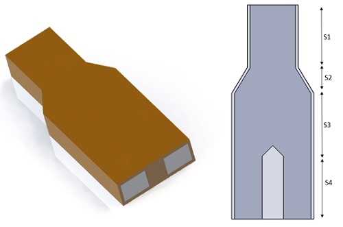
The proposed Waveguide power divider features three ports, enabling the input power to split into two equi-phasic and equi-amplitude signal outputs. Figure 2 displays the 3D geometrical structure of the outer copper housing with its air cavity, consisting of four sections. The first unit section (S1) utilizes a standard rectangular waveguide WR-284 tailored to the operational frequency (3.7 GHz in this instance, ensuring dominant mode propagation). This is succeeded by a tapered section (S2) and then a straight waveguide section (S3), ultimately bifurcating into two equal output arms. Detailed geometrical dimensions for each section can be found in Table 1.
| Section | Dimension (mm) | ||
| Section S1 | width=72.136 | height=34.036 | Length=100 |
| Section S2 | width=121 | height=34.036 | Length=40.54 |
| Section S3 | width=121 | height=34.036 | Length=100 |
| Section S4 (Arm1,2) | width=43.659 | height=34.036 | Length=100 |
Simulation Setup
The S-parameters solver of HFWorks is employed, integrated with thermal and structural analyses, operating within a frequency range of 3.45 GHz to 3.9 GHz. The material properties utilized are outlined in Table 2.
| Material | Relative permittivity | Dielectric loss tangent | Electrical conductivity (S/m) | Thermal conductivity (W/m.K) | Thermal expansion coefficient (1/K) | Elastic modulus (GPa) | Poisson`s ratio |
| Copper | 1 | 0 | 5.96E+7 | 401 | 1.6 E-5 | 110 | 0.343 |
Electromagnetic boundary conditions
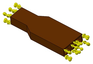
Wave port: The wave port boundary is applied to the input and output cavity ports.
Thermal boundary conditions
For an excitation power of $$ P_{\text{in}} = 500\,\mathrm{kW} $$ applied to the input port, a thermal boundary convection is applied to the inner faces of copper housing at an ambient temperature of 20°C and a convection coefficient set to $$\frac{11.5\,\mathrm{W}}{\mathrm{m}^2\cdot{}^\circ\mathrm{C}}$$.
Structural boundary conditions
Fixed boundary conditions are applied to the lateral faces of the copper housing, corresponding to both the input and output ports.
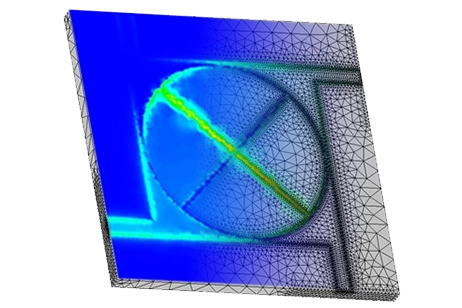
Mesh
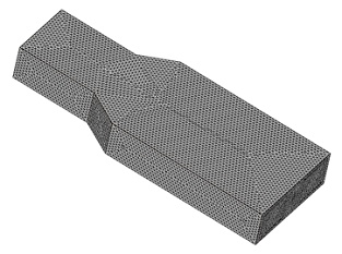
To improve result accuracy, a fine mesh control was applied to the studied model, as depicted in the following figure showcasing the meshed model.
Results
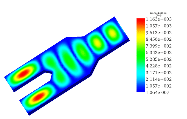
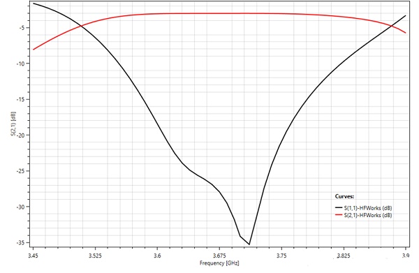
A fast sweep S-parameters study across the frequency range of 3.45 GHz to 3.9 GHz unveiled significant results, particularly highlighting a resonant frequency approximately at 3.7 GHz. The electric field distribution versus phase is illustrated in the subsequent figure, showcasing exemplary power division efficacy at 3.7 GHz.
The frequency response of the splitter is illustrated in the following 2D plot, displaying the return and insertion losses (S11-S21) results. Notably, it exhibits an acceptable response with losses under -20dB across a bandwidth of 140 MHz, centered around 3.7 GHz.
Thermal results
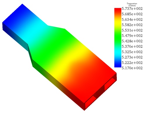
A steady-state thermal analysis of the power splitter was conducted at the resonant frequency of 3.7 GHz using the integrated Thermal Solver in HFWorks. With an input power excitation of 500 kW applied to the input port at an ambient temperature of 20°C and under specified thermal boundary conditions, the simulation yielded the following results:
Figure 7 illustrates the temperature distribution across the metallic housing, revealing a maximum temperature of 573°C along the output arms. Such a temperature rise is intolerable for the structure, posing safety risks in handling and detrimentally impacting its electromagnetic performance.
Structural results
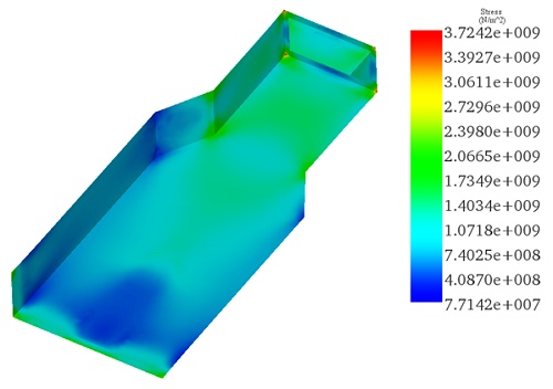
The Thermal solver seamlessly integrates with the Structural solver, allowing for a comprehensive analysis of thermal effects on the device's structural integrity and electromagnetic performance.
Displayed in the figure is the thermal Von Mises stress distribution across the metallic component. Notably, the analysis reveals maximum stress points reaching 3.72 E+9 N/m², accompanied by a maximum deformation of up to 1.2 mm. These findings underscore critical structural considerations, as excessive stress and deformation could compromise both the device's functionality and overall reliability.
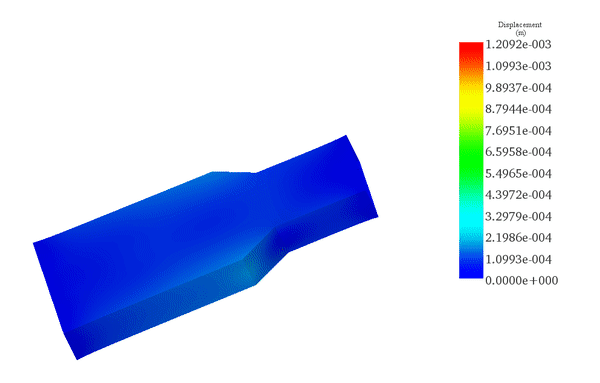
Even minor permanent deformations can degrade the S-parameters of the structure and shorten its operational lifespan with repeated use. Hence, the implementation of forced convection cooling is crucial to efficiently manage the temperature of the power divider, thereby sustaining its optimal efficiency over prolonged operational cycles. By actively dissipating heat, forced convection cooling mitigates stress-induced deformations, ensuring the device maintains its functionality and longevity under extended usage conditions.
Conclusion
This application note presents a detailed analysis of an RF Power Divider, highlighting its design, simulation, and the impact of thermal and structural stresses under operational conditions. Utilizing a waveguide-based structure known as the Folded H-plane tee junction, this three-port divider is optimized for high-frequency applications, demonstrating low loss and high power handling capabilities. The simulation, conducted with HFWorks, spans a frequency range of 3.45 GHz to 3.9 GHz, focusing on material properties, electromagnetic, thermal, and structural boundary conditions to ensure accuracy and reliability.
Significant findings include a resonant frequency at 3.7 GHz, with return and insertion losses under -20dB, showcasing effective power division. However, thermal analysis at an input power of 500 kW reveals a maximum temperature of 573°C in the output arms, indicating potential safety risks and performance degradation. Further, structural analysis points to maximum stress levels and deformation that could compromise the device's functionality and longevity. The study suggests implementing forced convection cooling to manage excessive heat, thereby maintaining the power divider's efficiency and structural integrity over extended operational periods.
This comprehensive analysis underscores the importance of integrating thermal and structural considerations in the design and optimization of RF power dividers, ensuring they meet the rigorous demands of high-power applications while maintaining safety and reliability.
References
[1]. Dixit, Harish V., et al. "Design data for quick development of folded H plane tee at high average power level." S?dhan?43.3 (2018): 33.