Bluetooth Antenna - Design and Simulation
In the field of wearable technology, particularly in smartwatches, Bluetooth antennas play a crucial role. This article focuses on the design and simulation of a Bluetooth antenna for smartwatches using HFWorks. It showcases the creation and simulation of two different antenna configurations - flat and bent - to examine their electromagnetic behaviors. The HFWorks Antenna analysis is utilized for simulating these antennas, providing insights into their performance in various forms. For a detailed exploration, you can refer to the source.
Flat Bluetooth antenna
Design and simulation
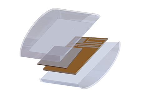
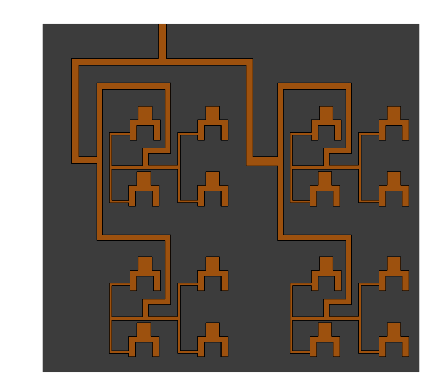
Figure 1 showcases a compact Bluetooth antenna design operating at 2.45GHz, energized through a microstrip line with a 50-ohm impedance. Utilizing FR4 for its base, noted for a relative permittivity of 4.5, and metals considered perfect electric conductors (PEC), this configuration is critical for optimal performance at the specified frequency. For an in-depth exploration and more information, refer to the source.

Figure 1 - Front and bottom view of the flat antenna.
Results
The simulated return loss (S11) for the flat Bluetooth antenna, conducted using HFWorks with the Fast Sweep Type, is depicted in Figure 2. The frequency sweep for this simulation ranges from 2GHz to 3GHz, and it demonstrates that the antenna resonates effectively at 2.45 GHz. This resonance point is crucial for the antenna's performance in its intended application. For more details and a visual representation, you can refer to the original source.
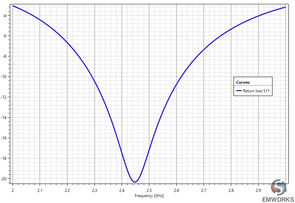
Figure 2 - Return loss S11 of the flat antenna (dB).
The Voltage Standing Wave Ratio (VSWR) is depicted in Figure 3. At 2.45 GHz the VSWR is less than 1.2
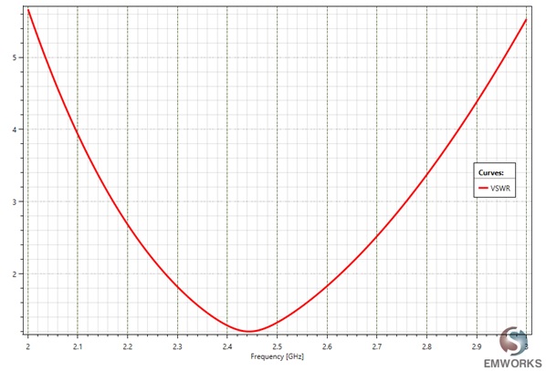
Figure 3 - 2D plot of the VSWR.
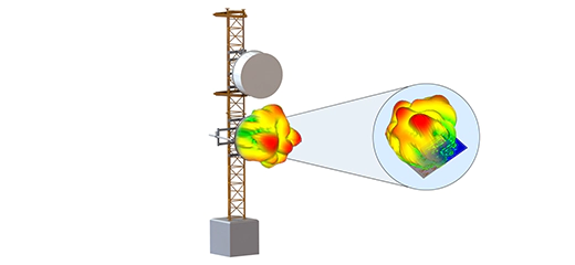
Polar plot views of the far field data are given in Figure 4 of the gain at 2.45GHz in the XZ, XY, and YZ planes.
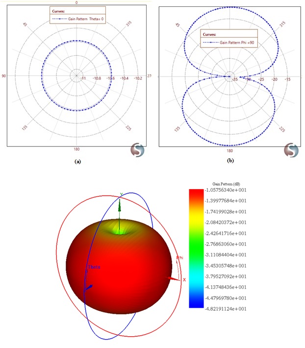
Figure 4 - 2D plot of the gain at 2.45 GHz in the XY, YZ and XZ planes.
Bent Bluetooth antenna
Design and simulation
In wearable electronics, assessing antenna performance under different bending conditions is crucial. Figure 5 displays the geometry of the bent Bluetooth antenna, highlighting these adaptations. For more detailed information and visual illustrations, please refer to the source.
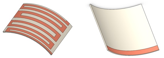
Figure 5 - The geometry of the bent antenna (top and bottom views).
The study includes simulations of various bending angles. These different configurations, as handled by HFWorks, are summarized in Table 1. This table provides an overview of how each configuration affects the antenna's performance. For a detailed view of these configurations and their impact, please refer to the source.
Table 1 -The different configurations simulated by HFWorks
| Name | Value |
| Configuration 1 | 10deg |
| Configuration 2 | 20deg |
| Configuration 3 | 30deg |
Results
The simulated return losses (S11) for each antenna configuration under different bending angles are illustrated in Figure 6. These simulations show that the bending angle significantly impacts the antenna's resonant frequency. This relationship is crucial in understanding how physical modifications affect the antenna's operational characteristics. For more detailed information and visual data, please refer to the original source.
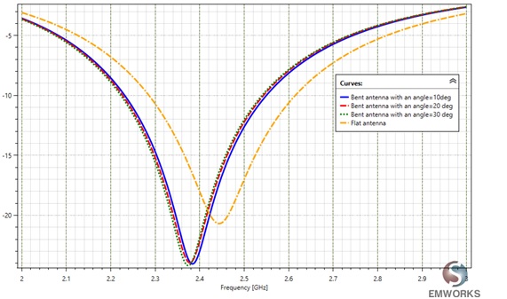
Figure 6 - The simulated return loss S11 for each configuration.
The study indicates that bending the antenna alters its resonant frequency to around 2.37 GHz, which falls outside the typical Bluetooth band, thus affecting the antenna's performance. Despite this change in resonance, the gain patterns of the various configurations, as shown in Figure 7, remain omnidirectional. However, the flat antenna configuration exhibits the highest gain value. This finding is significant for the design and application of antennas in wearable technology. For more detailed information and visual data, please refer to the source.
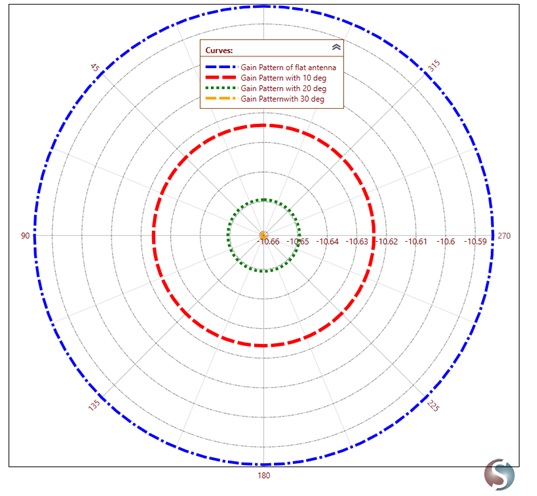
Figure 7 - The gain pattern of each configuration
Conclusion
This application note delves into the design and simulation of Bluetooth antennas for smartwatches, focusing on two configurations: flat and bent. Utilizing HFWorks for electromagnetic behavior analysis, the study evaluates the antennas' performance to optimize wearable technology. The flat antenna, operating at 2.45GHz with a 50-ohm microstrip line and made from FR4 and PEC materials, demonstrates optimal resonance and a low VSWR at the target frequency, ensuring efficient Bluetooth connectivity. Simulation results, including return loss and gain patterns, indicate the flat configuration's superior performance with an omnidirectional gain pattern, crucial for wearable device functionality.
Conversely, the bent antenna analysis reveals that bending angles significantly influence the resonant frequency, with a notable shift to 2.37 GHz, potentially impacting Bluetooth band compatibility. Despite these alterations, gain patterns remained omnidirectional across configurations, though the flat antenna exhibited the highest gain.