Microwave Heating of Asphalt Mixtures
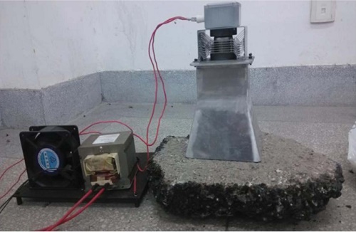
Microwave and RF heating are extensively used in industrial processes like drying, curing, and vulcanizing. Among their applications, RF heating plays a crucial role in maintaining road structures, particularly in the upkeep of asphalt mixtures for pavement repair. Asphalt mixtures, commonly utilized in road surfaces, parking lots, and airports, can deteriorate over time, leading to safety hazards and health issues. Microwave heating emerges as an efficient solution for rapid and uniform thermal maintenance, leveraging the dielectric loss properties of the asphalt material. A proposed RF heating setup involves a rectangular asphalt sample exposed to a coaxial feed pyramidal horn antenna operating within the frequency range of 700 MHz to 1300 MHz, as depicted in a reference [2] illustration.
CAD Model
HFWorks antenna analysis will be utilized to examine the proposed MW heating model in two phases:
1. The first phase involves evaluating the electromagnetic performance of the Horn antenna when irradiating a simple air box across the specified frequency range.
2. In the second phase, the analysis extends to include the Asphalt mixture sample, incorporating thermal coupling considerations within the same frequency band.
The CAD design of the model under study is depicted in the following figures:
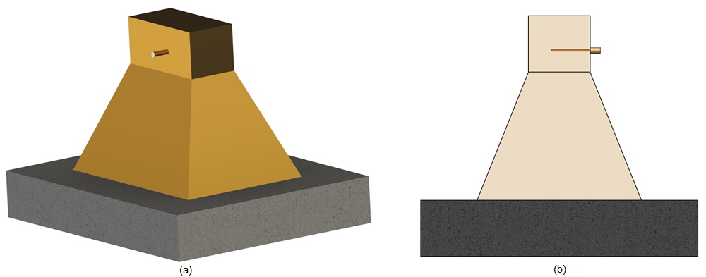
Table 1 - Dimensions of the studied antenna
| Part | Dimension (mm) | |||
| Aperture dimensions | E-plane:320 | H-plane:450 | ||
| Waveguide | Height:120 | Width:240 | Length:110 | |
| Horn length | 250 | |||
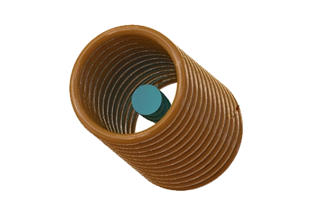
| Coax probe | Radius: 3.5 | Length:75 | ||
| Coax probe position from WG wall | 67.5 | |||
| Air/Asphalt sample dimensions | Height:540 | Width:670 | Length:110 | |
| Material | Relative permittivity | Dielectric loss tangent | Electrical conductivity (S/m) | Thermal conductivity (W/m. K) |
| Air | 1.00058986 | 0 | 0 | 0.024 |
| Copper | 1 | 0 | 5.96E7 | 401 |
| Teflon | 2.1 | 0 | 0 | 0.23 |
| Asphalt | 5.8 | 0.02 | 0 | 3.325 |
Electromagnetic boundary conditions
In the simulation setup:
- The wave port boundary is assigned to the dielectric input face of the coaxial feeding part. For pure TEM mode, a signal BC is applied to the input face of the coaxial inner conductor part.
- Perfect Electric Conductor (PEC) boundary conditions are applied to the outer faces of the horn cavity.
- Imperfect Electric Conductor (IPEC) boundary conditions are applied to the outer lateral Teflon face of the coaxial feeding part.
- Radiation boundary conditions are applied to the outer faces of the air/Asphalt box.
Study 1: Using Airbox
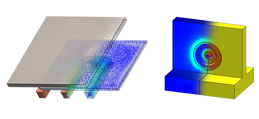
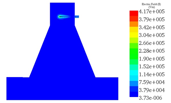
The initial antenna study investigates the radiation of the horn antenna in air. The simulation, conducted with an excitation power of 1 Watt, yielded the following results. The electric field distribution at 850 MHz is depicted in the following animated plot:
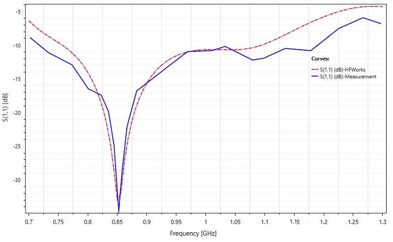
The return loss 2D plot results show a good agreement between the HFWorks and measurements for the working frequency band. The measured bandwidth for $$ \left| S_{11} \right| \leq 10\,\mathrm{dB} $$ is 56%.
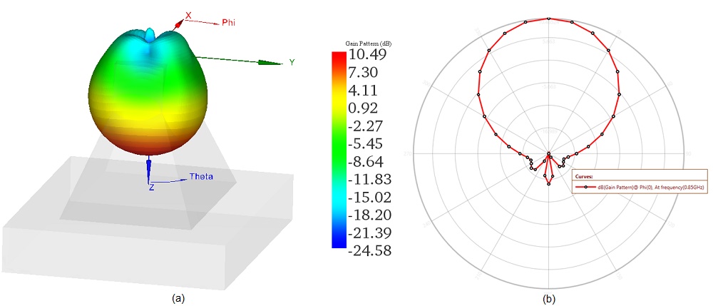
The maximum achieved gain at the operating frequency of 850 MHz is approximately 10.48 dB, aligning closely with the experimental results cited in Ref [2]. The following 2D and 3D plots illustrate the polar gain pattern results:
Study 2: Using Asphalt mixture sample
In the second analysis, we'll simulate the MW heating process of the Asphalt mixture using an excitation power of 800 Watts within the same frequency range. By coupling electromagnetic and heat transfer equations, we obtained the following results:
The first figure illustrates the electric field distribution from the horn antenna to the Asphalt sample at the operating frequency of 850 MHz:
(a)
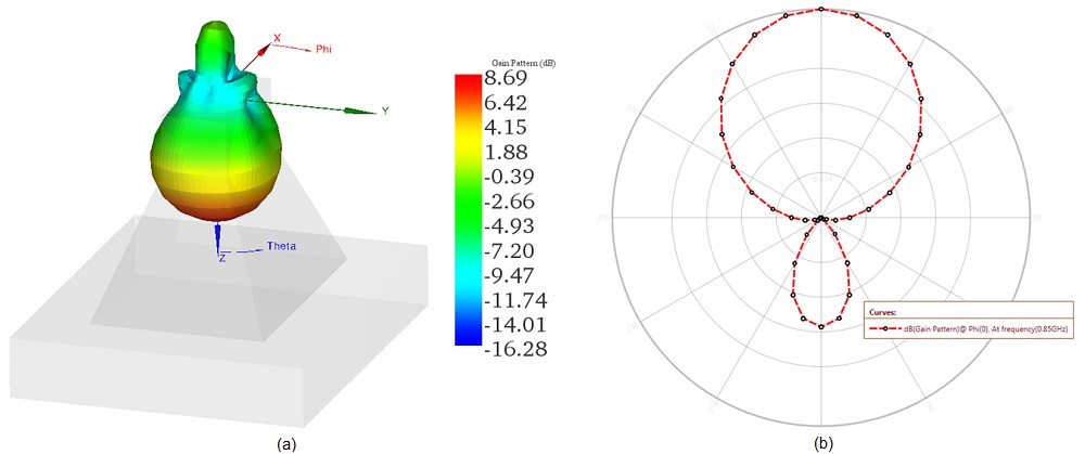
(b)
The subsequent figures depict the gain pattern illustration when the Asphalt is irradiated. An undesired back lobe is generated in the rear region, leading to a reduction in gain.
Thermal boundary conditions
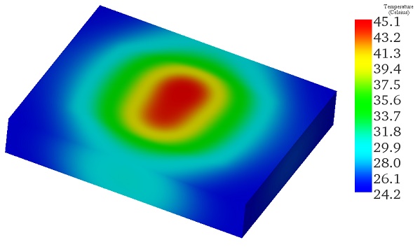
Steady-state thermal analysis is integrated with the electromagnetic study to estimate the temperature profile within the heated sample. A convection boundary condition is applied to the outer faces of the Asphalt mixture, with an ambient temperature of 22°C and a heat transfer coefficient set to 10 W/m²K, under an excitation power of 800 Watts. The resulting temperature distribution is illustrated in the following fringe plot:
Conclusion
This application note investigates the use of microwave (MW) and radio frequency (RF) heating for enhancing the maintenance and repair of asphalt mixtures, critical in road construction. Utilizing a coaxial feed pyramidal horn antenna, the study simulates the electromagnetic and thermal effects on asphalt within a 700 MHz to 1300 MHz frequency range. The research is conducted in two phases: first, analyzing the antenna's performance in air, and second, evaluating its effectiveness in heating an asphalt sample.
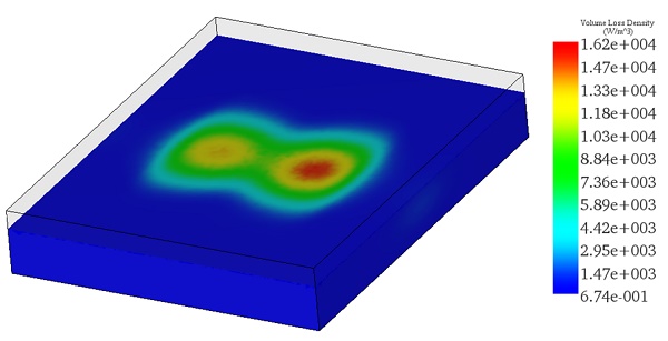
The findings highlight the antenna's efficient radiation pattern and substantial electric field distribution across the asphalt, indicating successful MW penetration and uniform heating at an excitation power of 800 Watts. Volume loss density and temperature distribution analyses confirm the method's capability for rapid and homogeneous heating, essential for repairing deteriorating asphalt effectively.
References
[1]- Kumar, Hemant, and Girish Kumar. "Coaxial feed pyramidal horn antenna with high efficiency." IETE Journal of Research 64.1 (2018): 51-58.
[2]- Sun, Tongsheng, and Lujun Chen. "Temperature field of asphalt mixture based on microwave heating." Journal of Microwave Power and Electromagnetic Energy 51.1 (2017): 59-70.
-Techniques.webp)