Wearable Antennas
Wearable antennas have revolutionized wireless communication in the realm of wearable devices, enabling seamless connectivity in various applications. From healthcare monitoring and sports tracking to augmented reality devices like Google Glass, these antennas play a vital role in facilitating wireless communication and data transfer. In this application note, we will focus specifically on designing an efficient antenna for Google Glass. We will explore the unique challenges and considerations involved in integrating antennas into the compact form factor of Google Glass, ensuring optimal performance and a seamless user experience.
Antenna Design Considerations for Google Glass
When designing an antenna for Google Glass, careful attention must be given to its size. Due to the compact form factor of Google Glass, the antenna needs to be designed to fit within limited space while maintaining optimal performance. Miniaturization techniques and innovative designs, such as microstrip or patch antennas, are commonly employed to achieve the desired balance between size and efficiency.
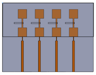
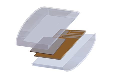
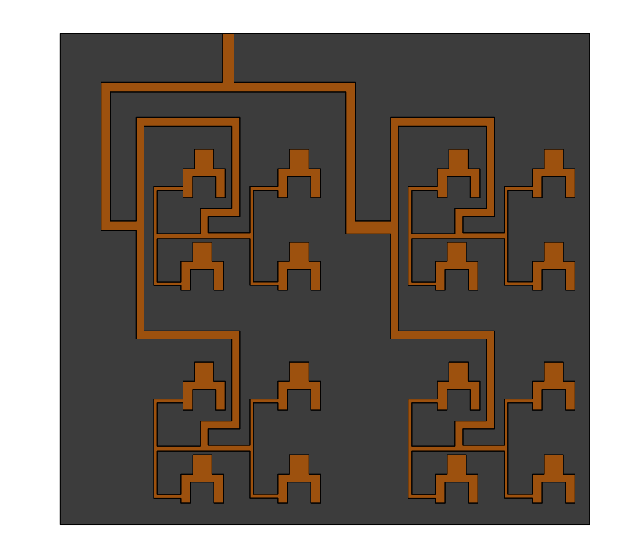
Fig. 1. Geometry of the mmWave Patch Antenna Array with Parasitic Elements
The patch antenna array has dimensions of 16.4 mm x 12 mm x 0.13 mm. The antenna design consists of three layers: a ground plane, a patch antenna array with feed lines, and parasitic elements. The impedance transformer is incorporated to match the impedance of the patch antenna with the 50 Ohm line. Additionally, a 70 Ohm series feed line excites the second patch element. Optimal impedance matching between the connected patches is achieved by adjusting the width of the series line to 0.23 mm. The parasitic elements are fed through electromagnetic coupling with the 70 Ohm line. For the antenna design, a Taconic TLY substrate with a thickness of 0.13 mm and dielectric properties (er = 2.2, tangLoss = 0.0009) was utilized. The antenna described above was simulated in two scenarios: one with the inclusion of parasitic elements and another without them.
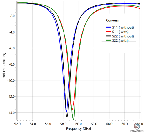
Fig.2. Return and Insertion Loss of the Antenna (dB)
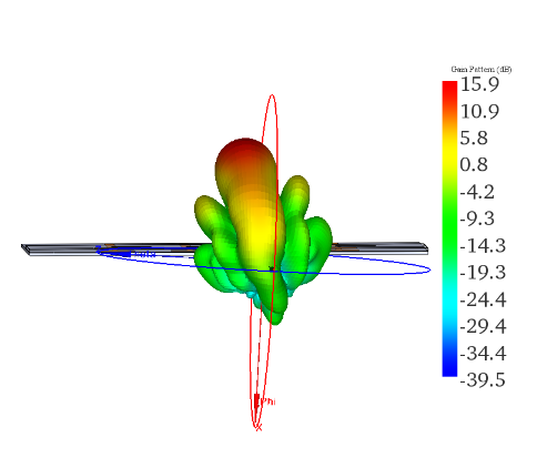
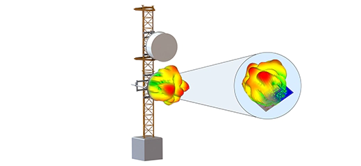
Fig.3. 3D Radiation Pattern of the Antenna with Parasitic Elements (59 GHz)
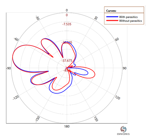
Fig.4. 2D Radiation Pattern of the Antenna (59 GHZ)
By analyzing the return and insertion loss plots of the antenna, it becomes evident that the resonant frequency remains relatively unchanged when the parasitic elements are incorporated. Furthermore, the 2D radiation pattern reveals that the antenna without parasitic elements exhibits a radiation null at approximately 60 degrees. However, the antenna with parasitic elements shows an improved radiation pattern with no null around 60 degrees. These findings indicate that the addition of parasitic elements enhances the coverage and performance of the antenna.
Antenna on Google Glass
When the antenna with parasitic elements is placed on Google Glass, it is important to consider the impact of the device itself on the antenna's performance. One notable effect is the "Google Glass effect," which refers to the influence of the surrounding materials and structures on the resonant frequency of the antenna.
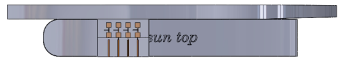
Fig.5. Antenna on Google Glass
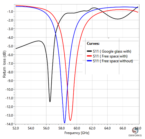
Fig.6. Return Loss of the Antenna
In the case of Google Glass, the resonant frequency of the antenna may experience a shift toward the lower frequency side. When the antenna is mounted on Google Glass, its radiation pattern can be influenced by the presence of the frame of the wearable device. However, the figures demonstrate that the radiation performance of the antenna remains largely unaffected, even when the beam is steered at different angles.
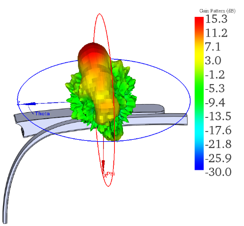
Fig.7. 3D Radiation Pattern (56.5 GHz)
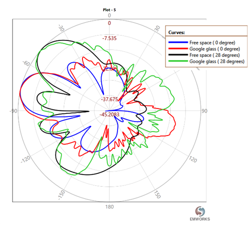
Fig.8. 2D Radiation Pattern of the Antenna (56.5 GHZ)
This robust radiation performance can be attributed to the antenna's design, which incorporates a full ground plane on the bottom. The presence of this ground plane helps minimize any disruptions caused by the wearable device frame, allowing the antenna to maintain its desired radiation characteristics. As a result, the antenna exhibits reliable wireless connectivity in practical wearable environments, ensuring consistent performance for users of Google Glass.
Conclusion
Designing efficient wearable antennas, including those for Google Glass, requires careful consideration of size constraints and the impact of the surrounding environment. The use of innovative design techniques, such as incorporating parasitic elements and optimizing resonance frequencies, can enhance antenna performance. HFWorks, a high-frequency electromagnetic virtual prototyping software, has been instrumental in addressing these challenges and improving the performance of wearable antennas. By leveraging the capabilities of HFWorks, engineers can simulate and optimize antenna designs, ensuring reliable wireless connectivity and enhancing the overall user experience of wearable devices like Google Glass.