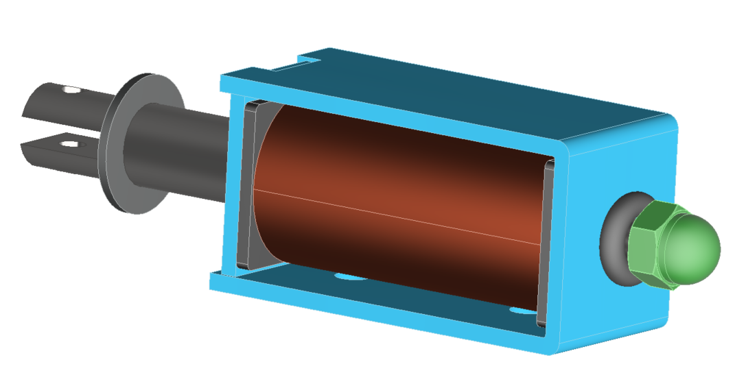
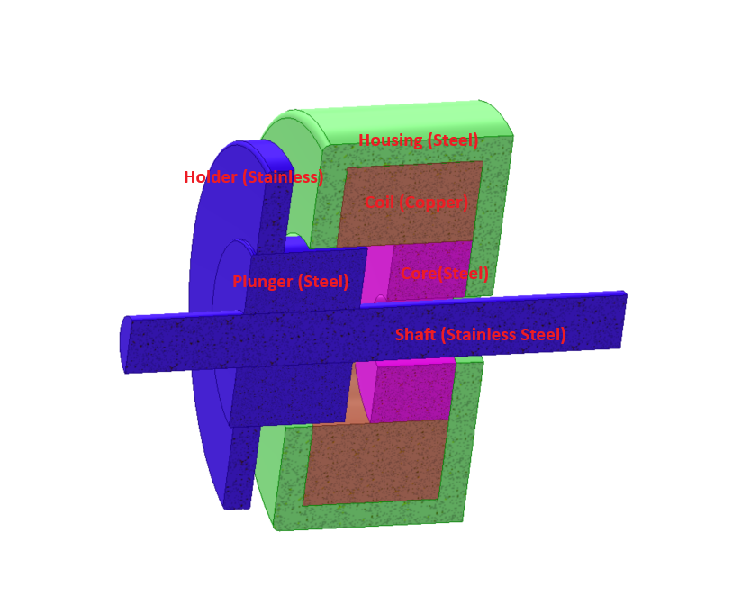
The Electromagnetic Relay
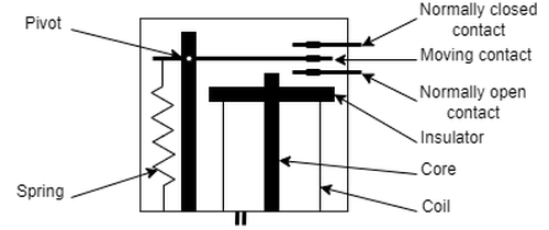
An electromagnetic relay is an electrically operated switching device. A coil generates a magnetic field that moves an armature, and the armature opens or closes a set of electrical contacts. The result is a component that lets a low-power control signal actuate an independent power circuit while providing galvanic isolation between the two.
In electric vehicles (EVs), electromagnetic relays and contactors manage the connection and disconnection of power circuits safely and reliably. They are implemented in battery management systems (BMS), charging interfaces, auxiliary power circuits, and thermal management units.
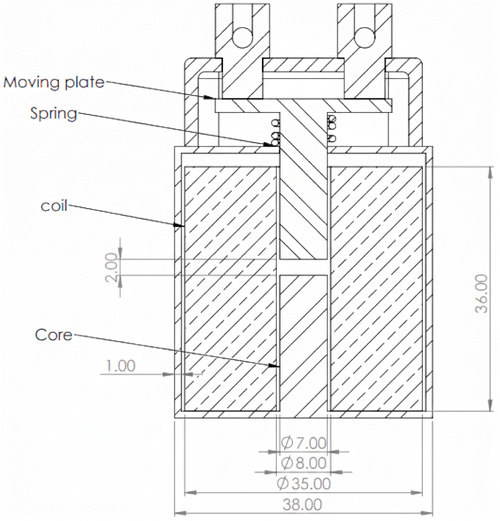
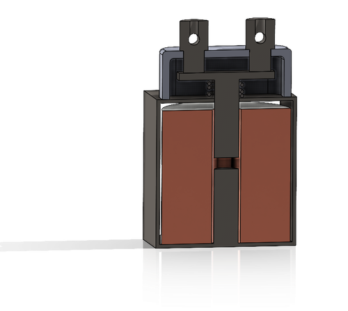
Figure 1: Electromagnetic relay geometry and dimensional layout.
The operating principle is simple. The engineering challenge lies in making the relay function reliably, predictably, and cost-effectively within strict spatial and physical constraints. This application note follows an electromagnetic relay through its development cycle and shows how a three-dimensional magnetostatic study in EMWorks EMAG answers a central design question: does the coil generate enough force to pull the armature in against its return spring, and with how much margin?
From Vehicle Requirements to Relay Specifications
Product development is an iterative cycle of design, testing, and refinement rather than a fixed sequence of steps. This iterative structure ensures technical traceability and eliminates late design bottlenecks. It starts with product definition: establishing the product requirements and system specifications, and performing the functional decomposition that connects performance needs to concrete technical choices.
Product Requirements: The Relay as a Subsystem
Within an EV architecture, relay requirements are dictated by system-level demands. As an example, a relay may need to switch a 400 V DC auxiliary load at a rated contact current of 80 A while limiting contact temperature rise and contact resistance. It must achieve rapid actuation, typically within milliseconds between coil energization and contact closure or separation. It must also maintain electrical clearance and creepage isolation between the low-voltage logic circuit and the high-voltage load, while withstanding thermal cycling and mechanical vibration.
The need analysis establishes technical targets covering electromagnetic force generation, mechanical motion, contact dynamics, thermal dissipation, electrical isolation, EMC, and environmental durability. These targets form the baseline for sizing the relay geometry, winding parameters, magnetic circuit, return spring, and contact materials.
System Specifications: The Relay as a System
Treating the relay as a system breaks the high-level requirements down into interrelated physical subsystems. for example, the coil must provide sufficient magnetomotive force (MMF) to ensure positive armature pull-in across the maximum working air gap, even under minimum supply voltage and with coil resistance elevated by thermal heating. The magnetic circuit must maintain adequate saturation flux density margins under worst-case magnetic loading while minimizing flux leakage, to maximize mechanical force per watt.
Where Simulation Fits in the Development Cycle
One of the most common representations of the development process is the V-cycle, which connects each engineering design phase to a corresponding verification and validation activity.
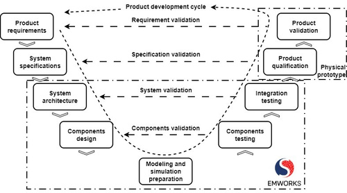
Integrating simulation into this cycle breaks the dependency on physical prototypes. With high-fidelity virtual models, engineering teams can detect design defects earlier, scale test scenarios across boundary conditions, and accelerate iterations while eliminating intermediate manufacturing costs. Physical prototyping then becomes the final validation step, executed only once the digital model satisfies all technical criteria.
System Architecture
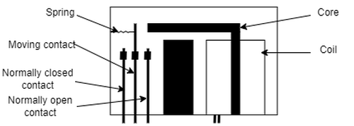
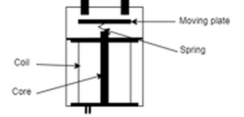
Once the design criteria are defined, the relay is divided into primary functional assemblies and candidate topologies are evaluated. Magnetic loss distribution varies substantially between them. A configuration with a shorter, optimized magnetic flux path lowers reluctance, requires fewer ampere-turns to generate the necessary attraction force, and consequently reduces Joule heating in the winding. Conversely, topologies with significant stray flux demand higher excitation current, driving up copper losses, and local flux concentrations may induce localized saturation and core losses.
Electromagnetic simulation allows rapid parametric comparison of candidate configurations in terms of reluctance, flux density uniformity, and losses, providing numerical justification for the selected architecture before the geometry is finalized.
 |  |  |
Component Design
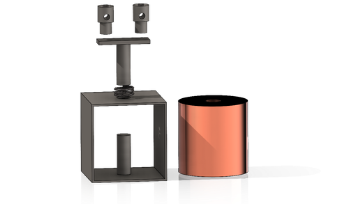
In this phase, individual sub-assemblies and components are dimensioned. In our study three components receive particular attention:
- Actuator coil. It provides the magnetomotive force necessary to establish flux across the magnetic circuit and generate the required dynamic pull-in force. Its geometry, wire gauge, and turn count are sized to ensure that the developed electromagnetic force consistently exceeds the opposing mechanical loads and air-gap reluctance, while maintaining sufficient static holding force in the closed position.
- Armature. Its cross-section and material are selected to prevent localized saturation bottlenecks.
- Magnetic core. It is sized and shaped to maximize magnetic permeance, provide a low-reluctance path for magnetic flux, and minimize leakage flux while avoiding premature core saturation under peak excitation. The interplay between coil excitation, core flux distribution, and armature force is precisely what the magnetostatic study described below evaluates.
Simulation preparation
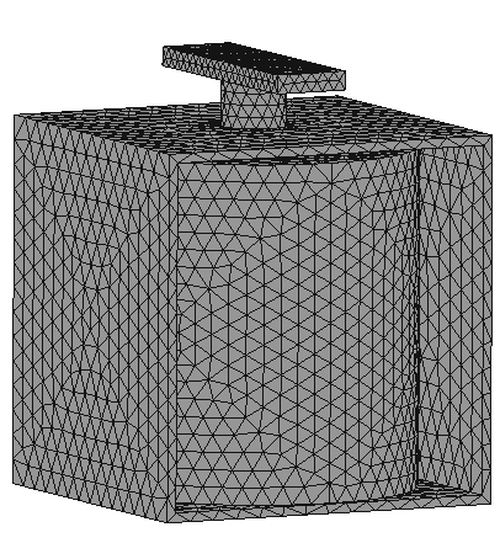
Before solving, the CAD geometry must be prepared so that the finite element model captures the relevant physics without unnecessary computational overhead. EMWorks EMAG allows engineers to defeature, simplify, and mesh mechanical models efficiently. For magnetostatic and transient electromagnetic analyses, non-magnetic hardware, non-conductive enclosures, minor fillets, and standard fasteners that do not carry flux or influence the magnetic path can be suppressed. This simplification reduces mesh density, accelerates convergence, and optimizes memory usage without sacrificing electromagnetic accuracy.
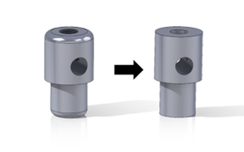
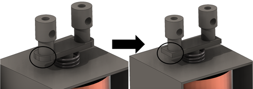
For the relay, the electromagnetic finite element model comprises the magnetically active solid parts and the surrounding medium:
- Active solid bodies: the excitation coil (modeled as two half-bodies for wound-coil path definition), the stationary magnetic core with its external return yoke frame, and the movable armature plate. Non-magnetic components, such as the mechanical return spring, mounting terminals and contacts, are excluded from the electromagnetic solution domain to optimize mesh size and numerical efficiency.
- Surrounding air domain: an enclosing air box that contains the entire assembly to resolve stray magnetic fields, air-gap fringing paths, and far-field boundary conditions.
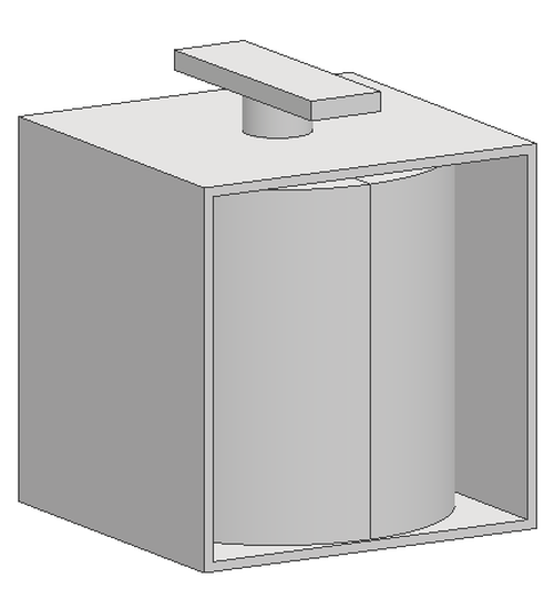
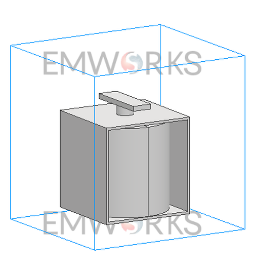
Figure 6: Electromagnetic simulation domain and surrounding boundary volume.
The relay was evaluated using a three-dimensional magnetostatic study in EMWorks EMAG. The coil is excited by a direct current (DC), so the resulting field distribution is time-invariant. The attraction force on the moving plate is calculated with the virtual work method, the following steps:
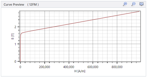
Material assignment to the winding, core, armature, and air domain.
| Component / Body | Material | Property assigned |
| Coil (2 bodies) | Copper | Default library conductivity |
| Core frame (1 body) | 12FM steel | Non-linear B–H curve |
| Moving plate (1 body) | 12FM steel | Non-linear B–H curve |
| Surrounding medium | Air | Relative permeability µr = 1.0 |
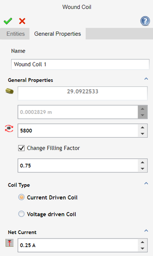
Coil excitation through a current-driven wound coil condition.
The magnetic circuit is excited by a single current-driven wound coil feature (Wound Coil 1) applied across the two coil bodies. Table 2 lists the parameters entered in the EMWorks EMAG pre-processor.
| Parameter | Value |
| Coil Type | Current Driven Wound Coil |
| Number of turns (N) | 5,800 |
| Wire gauge | 29.09 AWG |
| Conductor diameter | 0.2829 mm |
| Filling factor (kf) | 0.75 |
| Excitation current (I) | 0.25 A |
| Magnetomotive force (F = N · I) | 1,450 A·turns |
The moving armature plate is positioned at an initial working air gap of 2.0 mm, representing the closed-contact state. No symmetry conditions were imposed: the full geometry was computed inside the enclosing air box.
Meshing with a standard solid tetrahedral mesh.
The verification and validation Stages
The magnetostatic pull-in check is one verification activity within the wider development cycle.
Component Testing
Each sub-part is isolated and evaluated against its physical performance thresholds. The magnetic core undergoes magnetostatic analysis to verify that maximum flux density remains safely below the knee point of the material’s B–H curve, avoiding premature saturation.
Results
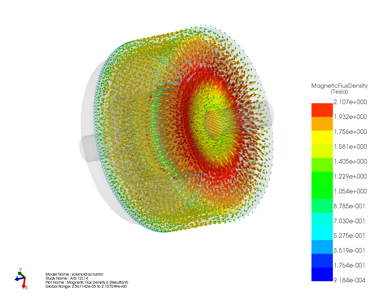
The magnetostatic solution provides the volumetric magnetic flux density, the spatial force density distribution, and the integrated virtual work forces acting on the movable armature plate.
Flux Density and Force Density
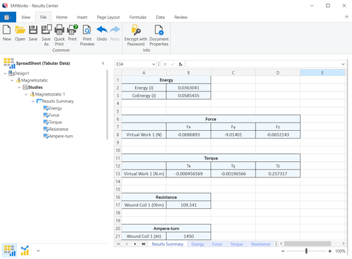
The magnetic flux density vector field and the axial force density (Fy component, in N/mm3) are both displayed on a central cutting plane. On that plane, the flux density colour scale peaks at 1.683 T. The EMWorks Results Center then collects the computed quantities in a summary table, which reports the 1,450 ampere-turns of Wound Coil 1 and a wound-coil resistance of 109.341 Ω, alongside the virtual work forces.
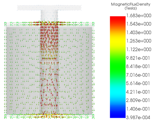
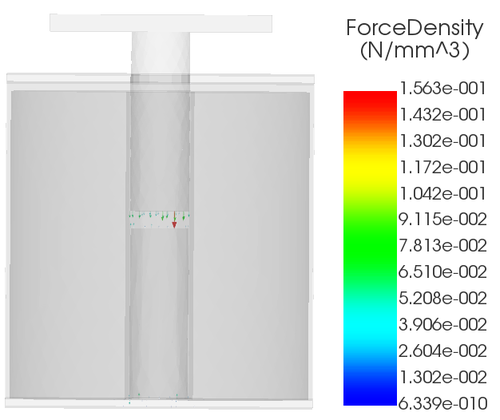
Figure 10: Magnetic flux density and axial force density distributions on a central cutting plane.
Integration Testing
Actuation Force on the Armature
Table 3 summarizes the force components acting on the movable plate.
| Component | Value (N) |
| Fx | −0.06869 |
| Fy (axial pull) | −9.01401 |
| Fz | −0.06521 |
The computed force is directed along the negative y-axis (Fy = -9.014 N), pulling the armature toward the stationary core. The lateral components Fx and Fz each remain below 0.07 N, less than 1% of the axial force, which confirms stable guided axial travel without significant misalignment loading.
Validation Against the Return Spring
The simulation was validated through a functional operating comparison against the catalogue characteristics of the return spring, part 70010. Table 4 summarizes the catalogue specifications.
| Parameter | Catalogue value |
| Outer diameter | 1.45 mm |
| Wire diameter | 0.20 mm |
| Total coils | 8.88 |
| Free length (L0) | 4.80 mm |
| Solid length (Ls) | 1.80 mm |
| Spring rate (k) | 0.70 N/mm |
| Suggested maximum deflection | 2.50 mm |
| Suggested maximum working load | 1.80 N |
The mechanical reaction of the spring follows: F = k x
With a stiffness of k=0.70 N/mm, the spring exerts 1.40 N at the end of the 2.0 mm stroke, well below its maximum recommended working load of 1.80 N. Table 5 sets this against the simulated magnetic pull.
| Operational parameter | Value | Basis |
| Stroke limit (air gap) | 2.0 mm | Physical gap to core face |
| Spring load at full stroke | 1.40 N | 2.0 mm × 0.70 N/mm |
| Spring load at solid length | 2.10 N | 3.0 mm × 0.70 N/mm |
| Simulated magnetic attraction (|Fy|) | 9.01 N | EMWorks EMAG solution |
| Net actuation reserve | +7.61 N | Ratio 6.4× (+543%) |
The simulated magnetic pull of 9.01 N exceeds the opposing spring force by a factor of 6.4, a reserve margin of +7.61 N. This confirms positive relay pull-in and contact opening throughout the travel path.
Product Qualification
Product qualification demonstrates that the finalized design satisfies its functional and environmental performance targets under realistic operating limits. In this project, qualification is limited to what the magnetostatic study can demonstrate: at the 2.0 mm open-contact air gap, the magnetic pull exceeds the return-spring reaction at full stroke by a factor of 6.4, while the spring operates below its 1.80 N recommended working load. Dynamic and kinematic simulations of contact bounce, actuation closing time, and contact wiping, as well as mechanical stress analyses of deflection, contact spring fatigue, and vibration response, were not part of this magnetostatic study. When engineering drawings and 3D CAD definitions are finalized with geometric dimensioning and tolerancing (GDT), they must preserve the 2.0 mm working air gap on which these results are based.
Product Validation
Physical prototype testing is the empirical check of the numerical predictions, examining contact resistance under load, thermal rise at continuous current, and mechanical endurance over high switching cycle counts. For this relay the magnetostatic results were validated through the functional operating comparison with the catalogue characteristics of return spring 70010 described above. Once prototype measurements are available, their correlation with the EMWorks EMAG model is the step that validates the simulation assumptions and closes the loop on the development cycle.
Conclusion
An electromagnetic relay is a compact device with demanding requirements: rapid actuation, electrical isolation between the low-voltage logic circuit and the high-voltage load, limited contact temperature rise and contact resistance, and durability under thermal cycling and vibration. Following the V-cycle, those requirements are decomposed into specifications for parts which together must satisfy them, and each design decision is paired with a verification activity.
In this study, the EMWorks EMAG model retained only the magnetically active bodies, enclosed in a surrounding air domain. The 3D magnetostatic analysis used a 5,800-turn coil carrying 0.25 A (1,450 A·turns), non-linear 12FM steel for the core and armature plate, and a 2.0 mm open-contact air gap. At component level, it provided the magnetic flux density and force density distributions on a central cutting plane; at integration level, it produced an axial pull of 9.014 N on the armature plate, with lateral components below 1% of the axial force. Compared against the 1.40 N reaction of catalogue spring 70010 at full stroke, the magnetic pull provides a 6.4× margin and a +7.61 N reserve, confirming positive pull-in and opening throughout the travel path.
The stages that remain beyond this magnetostatic study are coupled electromagnetic–thermal simulations of the coil, transient electromagnetic simulations of switching behavior, the dynamic, kinematic, and mechanical analyses of product qualification, and physical prototype testing correlated with the EMWorks EMAG model. Throughout that process, EMWorks provides electromagnetic and coupled multiphysics capabilities tailored to electromechanical product design, enabling teams to move from empirical trial-and-error toward predictive, data-driven engineering.
Reference
Compression Spring Part 70010: https://www.centuryspring.com/shop/70010cs