A Dielectric Loaded Waveguide Filter
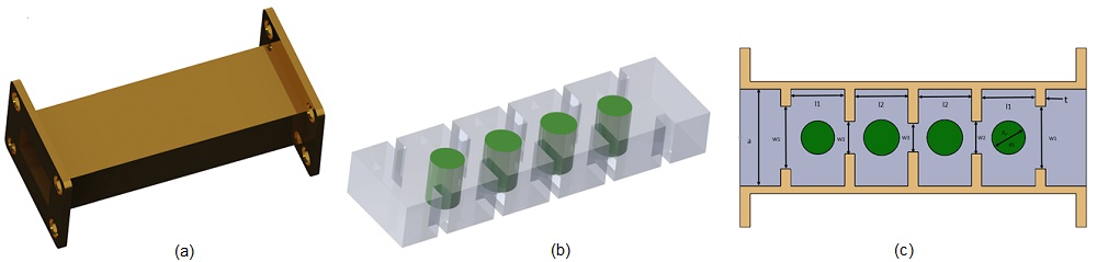
Efforts are underway to enhance the performance of rectangular waveguide H-plane filters, a popular choice for communication devices. These improvements aim to reduce mass and volume, increase out-of-band rejection, enhance thermal stability, and mitigate the risk of RF breakdown. The analyzed filter topology, proposed in Ref [1], features rectangular coupled waveguide cavities separated by inductive iris and loaded with cylindrical dielectric posts, as depicted in Figure 1. Using HFWorks, an FEM analysis examines the electromagnetic and thermal behavior of this topology in the frequency range of 10.5 GHz to 11.5 GHz, focusing on the effects of dielectric properties on power loss and thermal stability.
S-Parameters study
An S-Parameters study using HFWorks coupled with the thermal solver will predict electric and magnetic field intensities as well as loss distribution across the filter within the frequency range of 10.5 GHz to 11.5 GHz. Detailed dimensions and material properties are outlined in Tables 1 and 2, respectively.
| Part | Dimension (mm) | |||
| W1, W2, W3 | 12.27 | 6.4 | 5.62 | |
| l1, l2 | 10.58 | 10.47 | ||
| a, b | 19.05 | 9.525 | ||
| d1, d2 | 6.6 | 7.04 | ||
| t | 2 | |||
| Material | Relative permittivity | Dielectric loss tangent | Thermal conductivity (W/m. K) |
| Duroid RT6010 | 10.2 | 0.0023 | 0.086 |
| Cooper | 1 | 0 | 400 |
| Air | 1 | 0 | 0.024 |
Electromagnetic boundary conditions
The wave port boundary condition is applied to both the entry and exit waveguide faces and is fed with 1 Watt of microwave power.
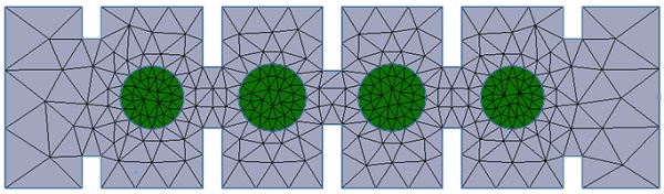
Mesh
A high-accuracy solver is utilized to ensure precise results with minimal mesh details. The entire meshed model is illustrated in the following figure.
Results
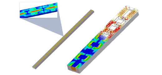
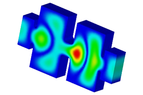
The S-parameters study simulation conducted with HFWorks yields the following results for a working frequency of 11 GHz: the first plot illustrates the electric field distribution within the studied filter with an excitation power set to 1 Watt.
(a)
(b)
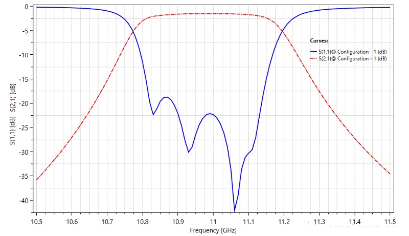
The return and insertion loss results are plotted versus frequency sweep in the next figure 4. The measured bandwidth for $$ \left| S_{11} \right| \leq 10\,\mathrm{dB} $$ is 36% and the return loss is better than 18 dB across the whole bandwidth. HFWorks simulation captures perfectly the rejected band.
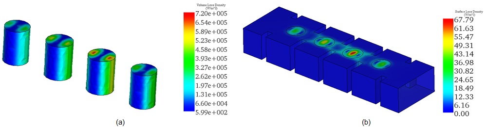
The loss analysis within HFWorks encompasses both conductor and dielectric losses. The following figure illustrates the volume and surface loss distributions for an excitation power of 1 Watt. Dielectric losses are notably significant within the loads compared to those across the conductor..
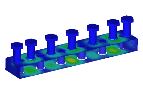
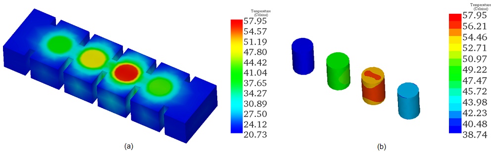
The presence of dielectric posts increases the volume losses within the studied design, which will be converted into heat during filter operation. HFWorks coupled to thermal analysis enables the prediction of its temperature profile for the working frequency of 11 GHz. A convection boundary condition is applied to the outer housing at ambient temperature with a convection coefficient set to 10 W/m²K. For low excitation power, the steady-state temperature reaches a maximum value of around 57°C inside the dielectric posts.
Conclusion
This application note explores advancements in rectangular waveguide H-plane filters loaded with cylindrical dielectric posts for communication devices, focusing on reducing mass and volume, improving out-of-band rejection and thermal stability, and minimizing RF breakdown risks. Employing HFWorks for finite element method (FEM) analysis within the 10.5 GHz to 11.5 GHz frequency range, the study assesses electromagnetic and thermal behaviors based on dielectric properties' impact on power loss and thermal stability. An S-Parameters study coupled with thermal analysis predicts electric and magnetic field intensities, loss distribution, and thermal effects, demonstrating significant dielectric losses within the filter when compared to conductor losses. The analysis reveals a bandwidth where the return loss is better than 18 dB, indicating efficient band rejection capabilities. Furthermore, thermal simulations predict a maximum steady-state temperature of approximately 57°C in the dielectric posts at an operational frequency of 11 GHz, highlighting the filter's thermal performance under low excitation power.
References
[1]. Aghayari, Hassan, et al. "Realization of dielectric loaded waveguide filter with substrate integrated waveguide technique based on incorporation of two substrates with different relative permittivity." AEU-International Journal of Electronics and Communications 86 (2018): 17-24.