A Waveguide Band-Pass Filter
This application note details a compact, high-performance 100 GHz rectangular waveguide band-pass filter (BPF) for THz applications, crucial in satellite and radio communications. Featuring inductive irises for enhanced circuitry, the design boasts low loss, high power handling, and easy integration. The four-pole filter includes dual-mode resonators and WR-10 waveguide interfaces, achieving precise frequency filtering with minimal interference. Thermal analysis ensures reliability under operational heat loads. Accompanying visuals provide a clear view of the BPF's advanced design and thermal properties.
![)- The schematic illustration [1] b)- cross-section view and c)-3D design inside SOLIDWORKS of the studied BPF](/ckfinder/userfiles/images/a%29-The%20schematic-illustration-%5B1%5D-b%29-cross-section-view-and-c%29-3D-design-inside-SOLIDWORKS-of-the-studied-BPF.jpg)
Table 1 - Dimensions of the BPF
| Dimension | d1 | d2 | d3 | d4 | a1 | a2 | a3 | a4 | t1 | t2 | t3 | r1 | r2 | r3 | l1 | l2 | l3 | b |
| Value (mm) | 1.165 |
2.695 |
2.82 |
1.165 |
2.54 |
5.345 |
5.02 |
2.54 |
0.33 |
0.92 |
0.25 |
0.14 |
0.24 |
0.09 |
1.346 |
1.14 |
1.19 |
1.27 |
Simulation Setup
The HFWorks S-parameters solver, paired with thermal analysis, targets the 94-106 GHz frequency range. This setup assesses electromagnetic and thermal responses, with essential material properties detailed in Table 2 for accurate simulation outcomes.
| Material | Relative permittivity | Dielectric loss tangent | Electrical conductivity (S/m) | Thermal conductivity (W/m. K) |
| Copper | 1 | 0 | 5.96E+7 | 401 |
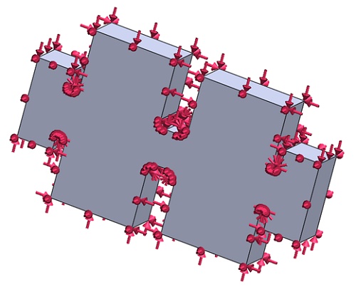
Electromagnetic boundary conditions
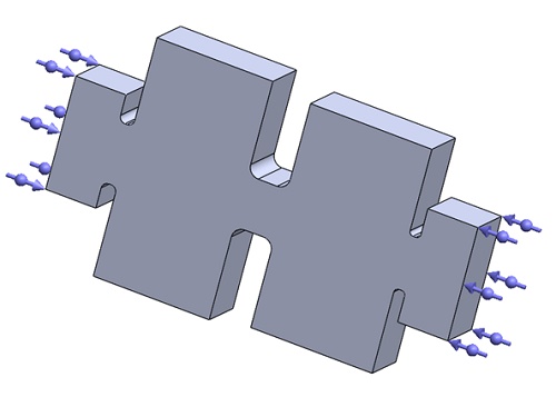
Wave port: The wave port boundary is applied to the input and output of the WR-10 cavity ports.
Thermal boundary conditions
For an excitation power of applied to the input port at 100 GHz, a thermal boundary convection is applied to the outer faces of the air cavity of the BPF at an ambient temperature of 22°C and a convection coefficient set to
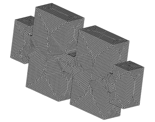
Mesh
In HFWorks, mesh control allows for varied element sizes in specific model areas, improving result accuracy. In this instance, fine mesh was applied throughout the air cavity, enhancing the simulation's precision, as shown in the upcoming figure of the meshed model.
Results
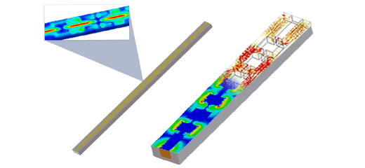
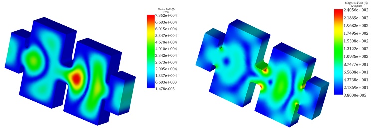
The S-parameter module in HFWorks is essential for analyzing high-frequency passive microwave structures, catering to a broad spectrum of applications. A rapid frequency sweep within the 94 GHz to 106 GHz range was conducted to investigate the resonant frequency near 100 GHz. This study yielded detailed insights into the electric and magnetic field distributions, which are visually depicted in the following 3D fringe plot:
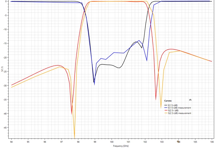
The subsequent figure illustrates the return and insertion loss plot against frequency, indicating a center frequency for the filter at 100.36 GHz, with a bandwidth under 10 dB of 28.33%. Additionally, two transmission zeros are identified at 97.6 GHz and 102.64 GHz, respectively, with the return loss exceeding -14 dB across the entire bandwidth.
A comparison of simulation and actual measurements shows a good match, highlighting a center frequency of 100.6 GHz, two transmission zeros at 97.77 GHz and 103.1 GHz, and a return loss better than -14 dB throughout the passband. The slight discrepancies in insertion and return loss figures could stem from surface irregularities or imperfect connections between the filter structure and the network measurement analyzer, suggesting areas for further investigation and adjustment to enhance accuracy.
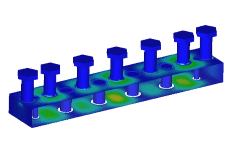
A steady-state thermal analysis, integrated with the S-parameters study, was conducted to evaluate the thermal performance of the band-pass filter (BPF). This analysis revealed the temperature distribution within the filter's air cavity, showing an average temperature of 35.87°C. This temperature profiling is crucial for understanding the filter's thermal stability and efficiency under operational conditions.
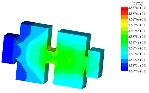
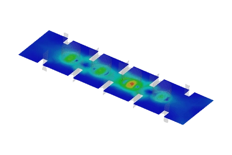
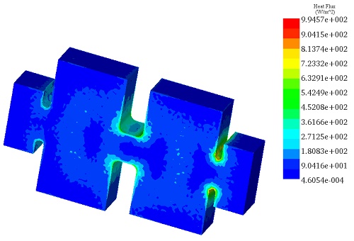
Figure 8 highlights the heat flux density across the band-pass filter, pinpointing the maximum value at the rounded corners of the inductive irises. This specific distribution indicates areas of heightened thermal activity, essential for assessing the filter's thermal management and identifying potential hotspots that could affect performance or reliability.
The precise thermal maps generated by HFWorks enable the prediction of the band-pass filter's (BPF) thermal behavior under a specified power excitation. This capability is instrumental in selecting appropriate materials during the initial design phases, ensuring the reliability and performance of the final product while preventing potential failures.
Conclusion
This application note presents a detailed study of a 100 GHz rectangular waveguide band-pass filter designed for terahertz (THz) applications, pivotal in satellite and radio communications. Employing inductive irises, the filter integrates dual-mode resonators and WR-10 waveguide interfaces to achieve precise frequency filtering with minimal interference, thus ensuring high performance. The Finite Element Method (FEM) simulation, performed with HFWorks, evaluates electromagnetic and thermal responses across the 94-106 GHz frequency range, ensuring the filter's reliability under operational heat loads. The results demonstrate the filter's effectiveness, with a center frequency of 100.36 GHz and bandwidth under 10 dB of 28.33%, alongside notable transmission zeros enhancing the filter's selectivity. Thermal analysis reveals an average temperature of 35.87°C within the filter's air cavity, identifying crucial thermal management areas. This comprehensive analysis underscores the filter's potential to enhance THz applications in satellite and radio communications, offering a compact, high-performance solution that combines low loss, high power handling, and seamless integration capabilities.
References
[1]. Xin, Wang, et al. "100 GHz waveguide band-pass filter employing UV-LIGA micromachining process." Microelectronics journal 69 (2017): 101-105.