The wireless system
Wireless systems span various applications like navigation, radar, TV, and mobile communications. Antennas play a critical role, especially in WLAN, covering multiple frequency bands. The 2.4GHz band is widely used, with antennas like Grid, Yagi, Biquad, Patch, Monopole, and Dipole. Designing efficient antennas is essential for better coverage in compact devices, ensuring cost-effectiveness, lightness, and integration ease. This study focuses on two WI-FI communication antennas for the 2.4GHz band: the Biquad antenna and the B-shaped dual-loop antenna.
Biquad antenna [1]-[2]
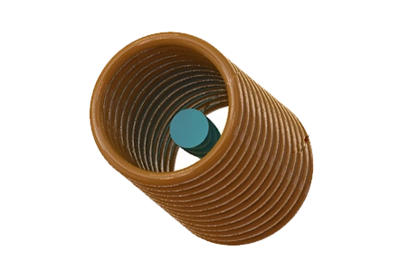
The Biquad antenna, known for its simplicity and effectiveness, features two interconnected square radiating elements, each sized at ¼ mid-band wavelength. This loop antenna design offers excellent directivity and gain for point-to-point communication. It is complemented by a rectangular metallic circular plate acting as a reflector, connected to a 50-ohm feeding coaxial cable.
| Part | Dimension (mm) |
| Wire diameter | 1.5 |
| Square side length | 32 |
| Inner conductor diameter | 1.5 |
| Outer Dielectric diameter | 5.1 |
| Reflector diameter | 140 |
| Reflector thickness | 2 |
| Coaxial cable length (Above the reflector) | 18 |
| Mid-band wavelength | 125 |
| Material | Relative permittivity | Dielectric loss tangent | Electrical conductivity (S/m) | Thermal conductivity (W/m. K) |
| Copper | 1 | 0 | 5.96E+7 | 401 |
| Aluminum | 1 | 0 | 3.5E+7 | 237 |
| Teflon | 2.1 | 0.001 | 0 | 0.23 |
Electromagnetic boundary conditions
Wave Port: Facilitating accurate analysis, it's applied to the coaxial antenna's dielectric input face.
Radiation: Crucial for antenna analysis, it truncates the computation domain and is applied to surrounding air box faces.
Perfect Electric Conductor (PEC): Ensures proper wave reflection and absorption, applied to coaxial cable and reflector surfaces.
Mesh
Results
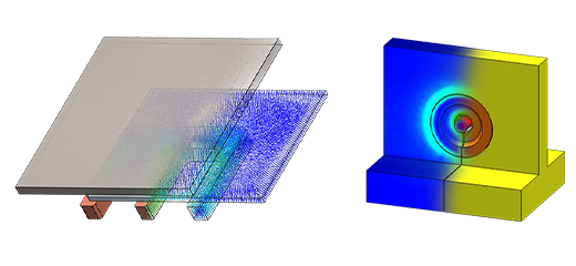
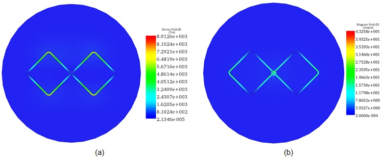
Utilizing the HFWorks Antenna solver at a 2.4 GHz frequency, coupled with thermal analysis, we examined the Electric and Magnetic field distributions for an excitation power of 1 Watt. The results are as follows:
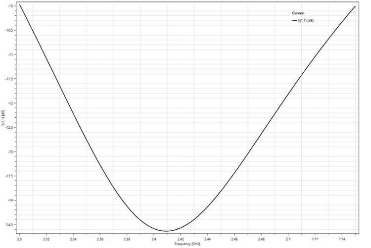
The depicted figure illustrates the return loss 2D plot outcomes spanning a frequency range from 2.3 GHz to 2.55 GHz. Notably, the center frequency of the filter registers at around 2.41 GHz, showcasing a bandwidth exhibiting a total under 10 dB.
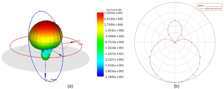
The metallic reflector strategically redirects electromagnetic waves towards the antenna's front (-Z-axis), enhancing gain and directivity while minimizing rearward radiation. With a gain of 10.5 dB, the Biquad antenna efficiently concentrates radio frequency energy. Figure 5 illustrates its radiation pattern, emphasizing directional transmission and effective power concentration in the desired direction.
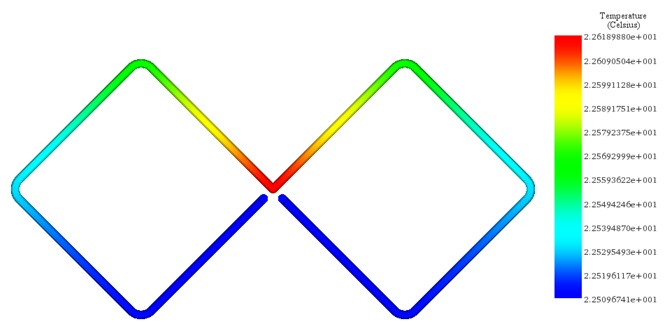
To evaluate the thermal behavior of the studied antenna under an applied excitation power of 5-Watt, convection BC is applied to the surrounding air box at an ambient temperature of 22°C and a convection coefficient set to $$ \frac{10\,\text{W}}{\mathrm{m}^2 \cdot \mathrm{C}} $$
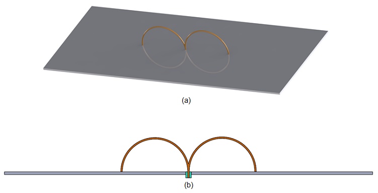
B-shaped dual loop antenna [3]:
Loop antennas, whether employed singly or in arrays, are highly versatile and cost-effective solutions for wireless communication needs. They come in various shapes, such as circular, triangular, or elliptical, offering flexibility in design and application.
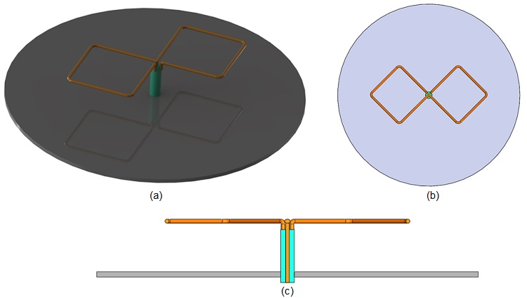
In our selected loop antenna design, we utilize interconnected loops positioned over a conductive plane, as depicted in Figure 7. Power is supplied via a low-loss 50-ohm coaxial cable.
| Part | Dimension (mm) |
| Wire diameter | 1 |
| Loop radius | 20 |
| Inner conductor diameter | 1 |
| Outer Dielectric diameter | 3.35 |
| Substrate dimensions | 220 x 100 x 1.6 |
| Mid-band wavelength | 125 |
The antenna utilizes copper wire for its metallic components, while Teflon material is employed in the dielectric coaxial part. Additionally, a glass-fiber FR4 substrate with dual metalized sides is incorporated into the design.
| Material | Relative permittivity | Dielectric loss tangent | Electrical conductivity (S/m) | Thermal conductivity (W/m. K) |
| FR-4 | 4.6 | 0 | 0 | 0.36 |
Electromagnetic boundary conditions
Wave Port: Applied to the dielectric input face of the coaxial antenna.
Radiation: Applied to the outer faces of the surrounding air box.
Perfect Electric Conductor (PEC): Applied to the top and bottom faces of the substrate part.
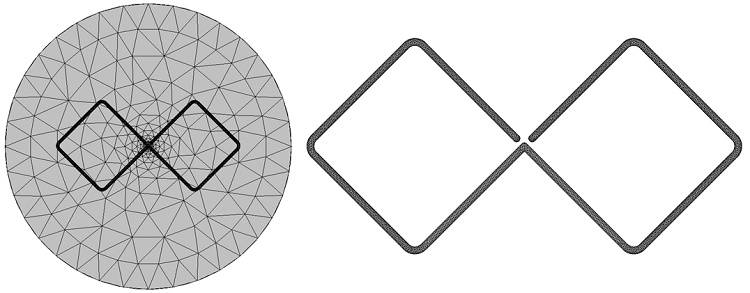
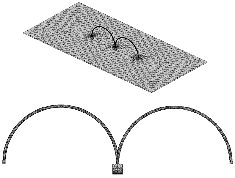
Mesh
Results
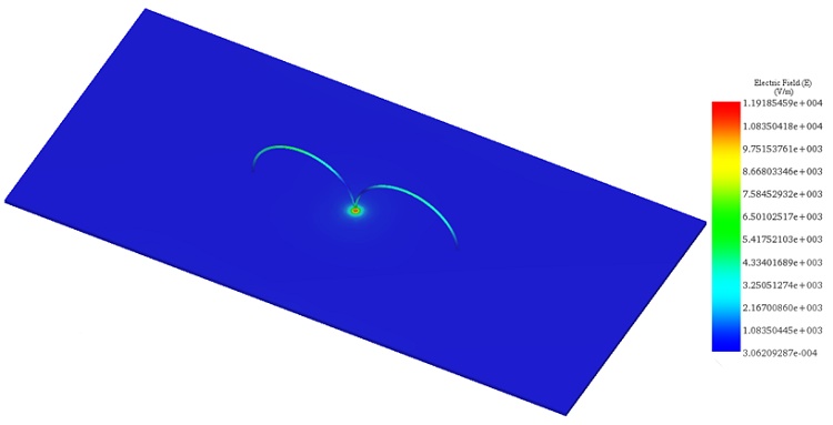
For the frequency range of [2GHz-3GHz], the simulation at 2.4 GHz displays the distribution of the electric field, as depicted in the following figure:
The subsequent figure depicts a 2D plot showcasing the return loss results plotted against frequency, with the nominal frequency set at 2.4GHz. It demonstrates that the B-shaped loop antenna achieves a bandwidth of 420 MHz for S11 < -10 dB.
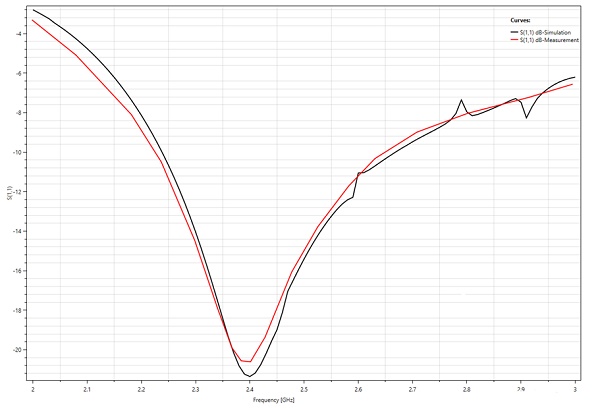
A comparison between HFWorks and measured results, as shown in Table 5, validates the strong agreement between simulation and experimental data.
| Results | Measurement | HFWorks simulation |
| Magnitude of S11-2.4GHz | 20 dB | 21 dB |
| Gain -2.4GHz | 6.31 dB | 5.98 dB |
| $$ \text{BW}_{-10\,\text{dB}} $$ | 40% | 42% |
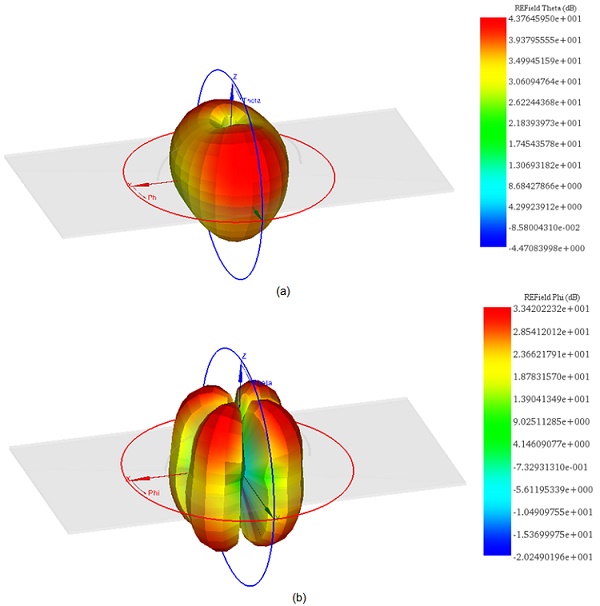
The radiation pattern provides insights into how the antenna radiates electromagnetic energy into space. It's a crucial aspect of antenna performance, showcasing characteristics like gain, directivity, and electric field distribution. Below, you'll find the E-field radiation pattern at 2.4 GHz:
To assess the thermal performance of the antenna under a 5-Watt excitation power, a convection boundary condition is applied to the surrounding air box. The ambient temperature is set at 22°C, with a convection coefficient specified as: $$ \frac{10\,\mathrm{W}}{\mathrm{m}^2 \cdot \mathrm{C}} $$
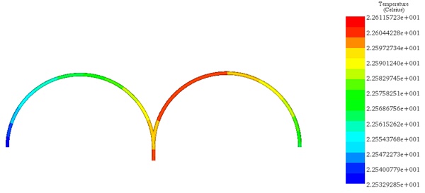
Figure 12 - Temperature distribution across the copper part at 2.4GHz.
Conclusion
This application note delves into wireless systems, particularly focusing on two antenna designs for the 2.4GHz band: the Biquad antenna and the B-shaped dual-loop antenna, pivotal for enhancing Wi-Fi communication. The Biquad antenna, known for its simplicity, comprises two interconnected square elements, providing excellent directivity and gain, ideal for point-to-point communication. A metallic reflector enhances its performance by focusing electromagnetic waves forward, achieving a notable gain of 10.5 dB. Conversely, the B-shaped dual-loop antenna offers a versatile design with interconnected loops over a conductive plane, demonstrating a bandwidth of 420 MHz for S11 < -10 dB, indicating efficient operation within the 2.4GHz band. Both antennas are analyzed using the HFWorks Antenna solver, examining electric and magnetic field distributions, return loss, gain patterns, and thermal behavior under a 5-watt excitation. The study showcases each antenna's distinct advantages, with the Biquad excelling in directivity and the B-shaped dual-loop showing broader bandwidth and good agreement between simulated and measured results.
References
[1]. Singh, Bablu Kumar and Amandeep Singh. “A Novel BiQuad Antenna for 2.4GHz Wireless Link Application : A Proposed Design.” (2012).
[2]. www.sjsu.edu/people/raymond.kwok/docs/project172/Omni_and_Biquad_antenna_2009.pdf
[3]. Chamorro-Posada, Pedro, et al. "A plug’n’play WiFi surface-mount dual-loop antenna." HardwareX 1 (2017): 46-53.
-Techniques.webp)