Spoke Resonator
Resonators amplify specific resonant frequencies, particularly in electromagnetic forms known as Cavity Resonators. These hollow metallic structures trap EM fields, fostering standing waves at certain frequencies. Essential in oscillators, transmitters, and radar filters, they also regulate charged particles in particle accelerators and magnetrons. The spoke resonator, a specialized type, is highlighted for particle acceleration.
CAD Model
Figure 1 displays the CAD model of the spoke resonator.
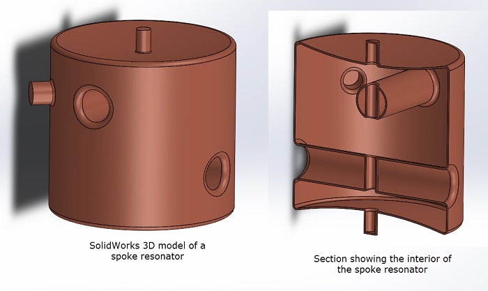
Figure 1 - Spoke resonator designed in SolidWorks
The resonator is engineered to achieve a primary resonant frequency of 325 MHz. The electromagnetic (EM) simulation objectives include:
-
Determining the first resonant frequency.
-
Calculating the quality factor (Qo factor).
This analysis is performed with HFWorks, a comprehensive 3D, CAD-embedded high-frequency simulation package.
Resonant Frequency Computation
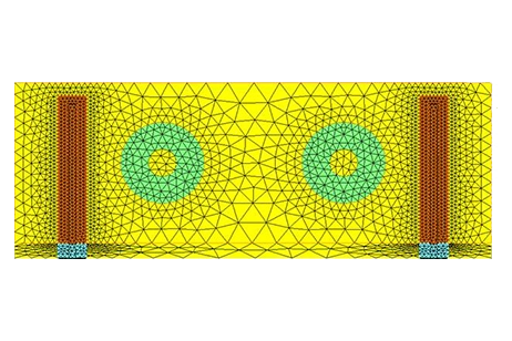
The simulation to determine resonant frequencies is conducted through a Resonance study, as shown in Figure 2. HFWorks is capable of calculating multiple resonant frequencies for any given structure. Specifically for the spoke resonator, the focus is on identifying the first mode, or the initial resonant frequency, and comparing it with experimental outcomes. HFWorks successfully computes the first resonant frequency at 323.02 MHz, closely aligning with the experimental result of 324.73 MHz, as illustrated in Figure 3.
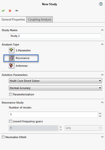
Figure 2- Creating a Resonance Study in HFWorks
Table 1 - Comparing the first resonance frequency
| HFWorks result | Test result | |
|---|---|---|
| First resonant frequency (MHz) | 323.02 | 324.73 |
Quality Factor (Qo) Computation
Beyond resonant frequencies, HFWorks also calculates the quality factor (Qo) and Stored Energy for the resonator at each resonant frequency. Figure 4 presents a table generated by HFWorks detailing these values for the first resonant frequency.
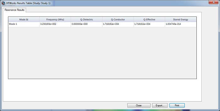
Figure 3 - Table showing 1st resonant frequency and Qo
3D Fields
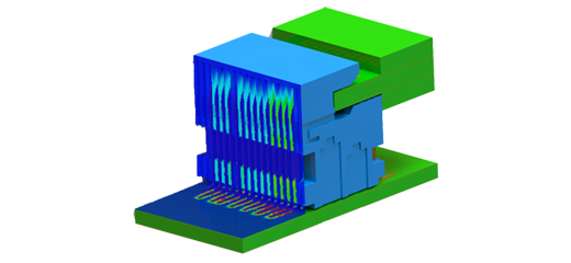
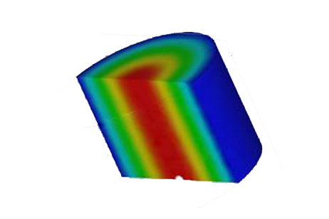
Figure 5 illustrates the Electric Field distribution within the resonator through a section plot, while Figure 6 depicts the Magnetic Field Intensity inside the resonator, also as a section plot. These 3D field results provide engineers with a qualitative analysis of the resonator's behavior.
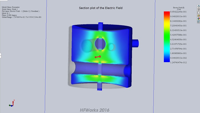
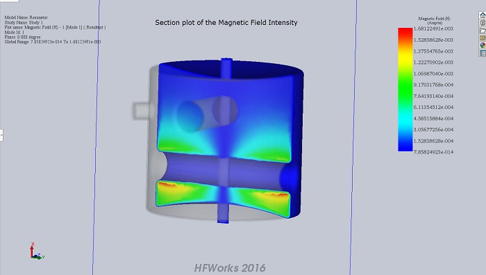
Figure 5 - Section plot of Magnetic Field Intensity
Conclusion
The spoke resonator, a specialized form of cavity resonator, plays a crucial role in amplifying specific resonant frequencies, particularly in particle acceleration applications. This study focuses on optimizing the design of a spoke resonator to achieve a primary resonant frequency of 325 MHz. Using HFWorks, a comprehensive 3D high-frequency simulation package, the resonant frequency and quality factor (Qo) are determined. Results show a close alignment between simulated and experimental resonant frequencies, validating the accuracy of the simulation. Additionally, 3D field visualizations provide insights into the electric and magnetic field distributions within the resonator, aiding engineers in understanding its behavior. Overall, this study highlights the importance of precise design and simulation techniques in optimizing the performance of spoke resonators for particle acceleration applications.
References
G. Lanfranco , G. Apollinari, I.V. Gonin, T.N. Khabiboulline, G. Romanov, R. Wagner (2007). PRODUCTION OF 325 MHZ SINGLE-SPOKE RESONATORS AT FNAL. Proceedings of PAC07, Albuquerque, New Mexico, USA. Retrieved from https://accelconf.web.cern.ch/accelconf/p07/PAPERS/WEPMN099.PDF