EMI/EMC Challenges and Solutions in Modern Vehicle Electronics
The rise of electronic and wireless technologies in modern vehicles has heightened Electromagnetic Interference (EMI) and Compatibility (EMC) concerns. These challenges arise from both densely packed internal electronics and external electromagnetic sources. The integration of diverse systems—ranging from Wi-Fi and GPS to advanced driving aids—increases the potential for interference, underscoring the importance of early EMI/EMC mitigation. Electromagnetic simulation is key, allowing for early identification and resolution of issues through virtual models. This strategy ensures optimized layouts and effective shielding, critical for maintaining seamless operation and compatibility of vehicle electronics.
Power Cables in Automotive Environment
The figures below illustrate two power cables, each measuring 2 meters in length. Our analysis will concentrate on identifying and addressing Electromagnetic Interference (EMI) challenges specifically related to common mode noise affecting these cables.
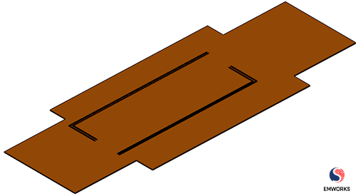
Fig. 1. Power Cables
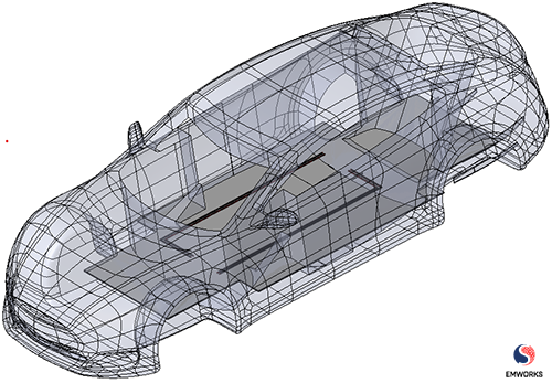
Fig. 2. Power Cables inside a Vehicle
Crosstalk
Crosstalk in-vehicle power cables cause undesired electromagnetic interactions, leading to interference and performance degradation. Common mode interference is particularly problematic, generating significant Electromagnetic Interference (EMI) that affects electronic system reliability and performance. The graphs below demonstrate that common mode noise results in greater EMI in the affected line than differential mode noise.
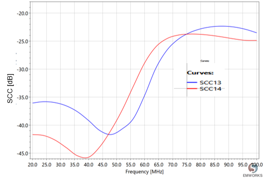
Fig. 3. Crosstalk (Common Mode)
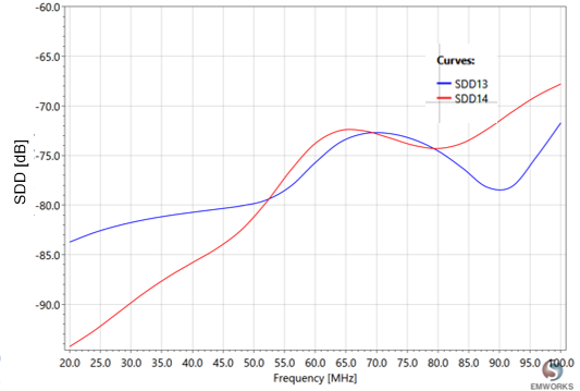
Fig. 4. Crosstalk (Differential-Mode)
Radiated Emissions
In addition to crosstalk, radiated emissions from power cables are a critical EMI concern, affecting automotive system functionality. Analyzing these emissions, especially from common mode signals, is key to maintaining electromagnetic compatibility. When cable lengths approach ?/2 or its multiples, they act as unintended antennas, emitting electromagnetic waves and risking interference with vehicle electronics. The graphs clearly show that at 76 MHz, the cables resonate, emitting higher levels of electromagnetic radiation than observed at 20 MHz.
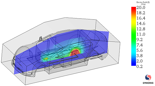
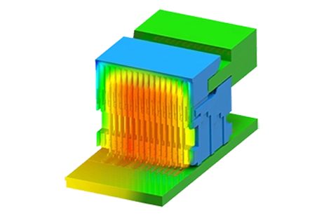
Fig. 5. E-Field due to Common-Mode Aggressor (20 MHz)
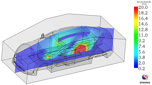
Fig. 6. E-Field due to Common-Mode Aggressor (76 MHz)
Immunity Testing
Immunity testing is vital for automotive electronics, ensuring they resist electromagnetic fields and radiofrequency interference effectively. It measures the systems' ability to endure disturbances like electromagnetic pulses, maintaining functionality. Here, power cables and a vehicle undergo testing in an anechoic chamber, evaluating their performance against electric fields from a biconical antenna.
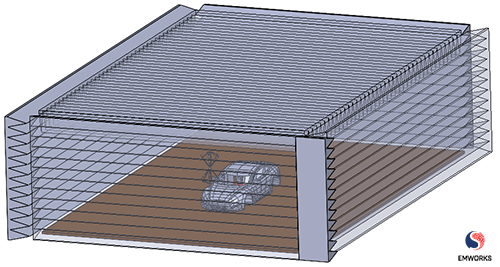
Fig. 7. Car Inside Semi-Anechoic Chamber
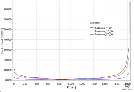
Fig. 8. E-Field Induced by the Antenna in the Power Cable (76 MHz)
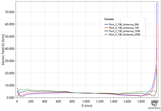
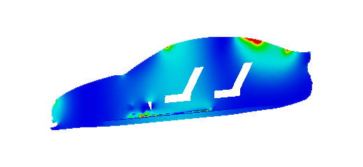
Fig. 9. E-Field Distribution in the Power Cable in the Presence of the Antenna (76 MHz)
The plots illustrate the field distribution at the resonant frequency of 76 MHz, comparing scenarios with and without a biconical antenna. At this frequency, power cables act as inadvertent antennas, capturing external signals and inducing noise within the system.
In the bottom figures, we can clearly notice a destructive interference caused by the antenna.
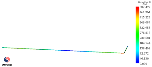
Fig. 10. 3D E-Field Distribution in the Power Cable (76 MHz, without the Antenna)

Fig. 11. 3D E-Field Distribution in the Power Cable (76 MHz, with the Antenna)
The plots reveal that at 20 MHz, the power cables operate efficiently. Yet, at 76 MHz, nearing wavelengths similar to their lengths, they start to behave like antennas, receiving and emitting interference that affects adjacent automotive devices.
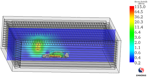
Fig. 12. The Operation of Power Cables in the Presence of the Antenna (20 MHz)
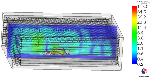
Fig. 13. The Operation of Power Cables in the Presence of the Antenna (76 MHz)
Conclusion
This application note addresses EMI and EMC challenges in automotive systems, focusing on mitigating common mode noise in 2-meter power cables. It highlights the importance of early intervention in design to prevent electromagnetic interference, particularly from crosstalk and radiated emissions, which can compromise vehicle electronics functionality. Immunity testing is emphasized as a critical measure for assessing system resilience against external electromagnetic disturbances. Through analysis and graphical evidence, it demonstrates how power cables can act as unintentional antennas, particularly at 76 MHz, leading to increased electromagnetic radiation and potential system interference. The note provides essential insights into ensuring electromagnetic compatibility and enhancing the reliability of automotive electronics.
References
[1] https://www.electronicsworld.co.uk/filtering-common-mode-noise-in-automotive-environments/30700
[2] https://transientspecialists.com/blogs/blog/automotive-vehicle-emc-emi-testing-overview-testing-standards-faq
[3] https://lbagroup.com/blog/emc-test-snapshot
[4] https://incompliancemag.com/article/radiated-emissions-measurements-oats-and-alse-methods
[5] https://premierfilters.medium.com/emi-and-emc-how-they-are-differ-55008a97ed11
[6] https://www.monolithicpower.com/en/emi-generation-propagation-and-supression-in-automotive-electronics-part-i