

EMC
Electromagnetic Compatibility (EMC) is vital for modern electronic design due to higher chip density and frequencies. This article explores how HFWorks analyzes EMC in Intel Dual Die CPUs at 2.05 GHz and 4.9 GHz. It covers electrical (S11, fields) and thermal (temperature distribution) results, with a focus on heatsink effects.
Simulation of the Dual Die CPU
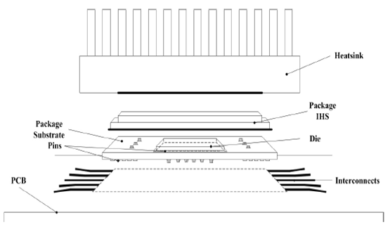
Figure 1 illustrates the Intel dual-die processor, including packaging, interconnects, and a heatsink. The study simplifies the internal chip interconnections, focusing on a simplified version in Figure 2, where the dual processor is modeled as a microstrip patch antenna with two coaxial feeds, resembling the actual chip structure.
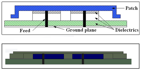
The pins and interconnections in the integrated circuit are represented by two coaxial feeds in Figures 1 and 2. The precise placement of these feeds significantly impacts the model's performance. The simulation employs dimensions and material properties detailed in Tables 1 and 2. Figure 3 displays the CAD model of the structure and the surrounding air region.
| Name | Typical (mm) |
|---|---|
| Height of Heatsink HH | Variable |
| Height of IHS | 1.65 |
| Height of Die | 1.15 |
| Height of substrate | 1.25 |
| Depth of TIM | 0.1 |
| Depth of Die attach material | 0.1 |
| Depth of IHS Sealant | 0.1 |
| Length of Heatsink | 67.5 |
| Width of Heatsink | 67.5 |
| Length of Die | 11.9 |
| Width of Die | 9.0 |
| Length of substrate | 37.5 |
| Width of substrate | 37.5 |
| Length of IHS External | 34 |
| Width of IHS External | 34 |
| Length of IHS Internal | 26 |
| Width of IHS Internal | 26 |
| Name | Materials | Permittivity | Conductivity(Siemens/m) |
|---|---|---|---|
| Substrate | FR4 epoxy | 4.4 | 0 |
| Die | Silicon dioxide | 4 | 0 |
| IHS | Aluminum | 1 | 3.8x10⁷ |
| Heatsink | Aluminum | 1 | 3.8x10⁷ |
| TIM | Silicone | 1.8 | 0 |
| Die attach material | Silver | 1 | 6.1x10⁷ |
| IHS Sealant | Epoxy | 1.8 | 0 |
The CPU's antenna model is excited through two circular wave ports with a specific impedance. These ports are positioned at the substrate's bottom and connected to copper coaxial feeds that make contact with the IHS [1].
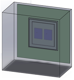
Figure 3 - 3D model of Intel Dual Die CPU processor with Heatsink
Simulation and results
A. Effects of the Heatsink
The simulation compares results with and without the CPU heatsink. Without the heatsink, resonant frequencies are 2.05 GHz (-11.45 dB) and 4.9 GHz (-20.54 dB) at port 1, and 2.05 GHz (-4.32 dB) and 4.9 GHz (-18.83 dB) at port 2. With the heatsink, resonant frequencies are 2.3 GHz (-25.83 dB) and 5.45 GHz (-12.90 dB) at port 1, and 2.3 GHz (-3.41 dB) and 5.45 GHz (-13.45 dB) at port 2. Figure 4 and Figure 5 demonstrate that HFWorks results closely match measured data.
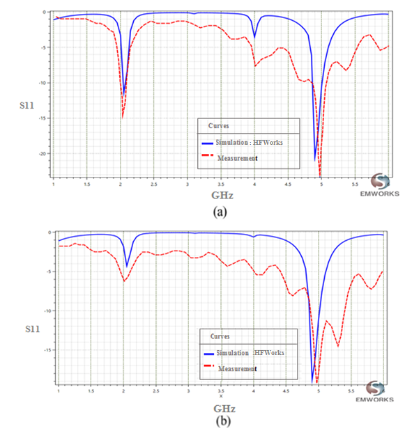
Figure 4 - (a) Reflection coefficient at port1. (b) Reflection coefficient at port2.
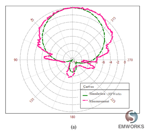
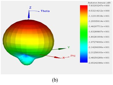
Figure 5 - (a)2D plot of radiation pattern at 2.05 GHz, (b) 3D plot of radiation pattern at 2.05 GHz
B. Height of Heatsink
Figure 3 shows a simplified heatsink as a solid block without fins. Various simulations were conducted to analyze the impact of heatsink height on field and circuit results, aiming for an optimized Dual Die CPU with a heatsink. Table 1 reveals that the heatsink's height has a minimal effect on the reflection coefficient at both port 1 and port 2. Consequently, the Intel dual die CPU's resonant frequency and scattering parameters are primarily determined by its internal structure, rather than the mounted heatsink.
| Simulation Setup HFW (Port1) |
Reflection coefficient | |
| GHz | dB | |
| Height of Heatsink HH=37mm |
1.75 | -16.69169 |
| 5.525 | -6.11 | |
| Height of Heatsink HH=42mm |
1.75 | -16.74 |
| 5.525 | -6.09 | |
| Height of Heatsink HH=47mm |
1.75 | -25.28 |
| 5.525 | -11.21 | |
| Simulation Setup HFW (port2) |
Reflection coefficient | |
| GHz | dB | |
| Height of Heatsink HH=37mm |
1.75 | -8.91 |
| 5.525 | -20.2224 | |
| Height of Heatsink HH=42mm |
1.75 | -11.38 |
| 5.525 | -13.10 | |
| Height of Heatsink HH=47mm |
1.75 | -11.42 |
| 5.525 | -12.25 | |
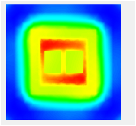
C. Heat Simulation
Figure 6 shows the temperature distribution in the CPU due to the conductor and dielectric losses of the modeled structure.
Conclusion
This application note explores the significance of Electromagnetic Compatibility (EMC) in modern electronic design, focusing on an Intel Dual Die CPU's EMC analysis at frequencies of 2.05 GHz and 4.9 GHz using HFWorks software. By simulating the electrical and thermal behaviors of the CPU, including the effects of a heatsink, the study provides insights into optimizing electronic components for improved EMC performance. The simulation models the CPU as a microstrip patch antenna, emphasizing the impact of heatsink presence on resonant frequencies and thermal distribution within the CPU. The results demonstrate a shift in resonant frequencies when a heatsink is used, underscoring the minimal effect of heatsink height on electromagnetic properties but its significant role in thermal management. The close match between HFWorks simulation results and measured data validates the effectiveness of this simulation approach in assessing and enhancing EMC in complex electronic designs like the Intel Dual Die CPU. This study highlights the critical role of simulation tools in addressing EMC challenges in high-density, high-frequency electronic components.
References
[1] Boyuan Zhu, Junwei Lu, and Erping Li, “Electromagnetic Compatibility Benchmark-Modeling Approach for a Dual-Die CPU”, IEEE Transactions on Electromagnetic Compatibility, February 2011, pp.91-98.
-enhance-chip-performance-and-efficiency.webp)

