5G antenna simulation
The demand for high-speed mobile communication is on the rise due to smart devices and 5G technology. This article demonstrates how HFWorks enables engineers to design 5G antennas, focusing on a Dual-Band mm-wave antenna simulation.
A 5G antenna model
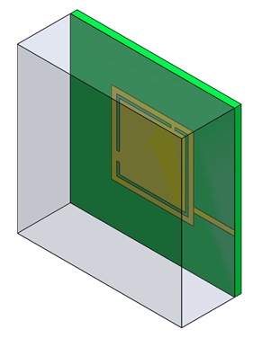
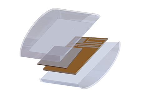
Figure 1 - 3D model of Dual Band antenna for 5G applications
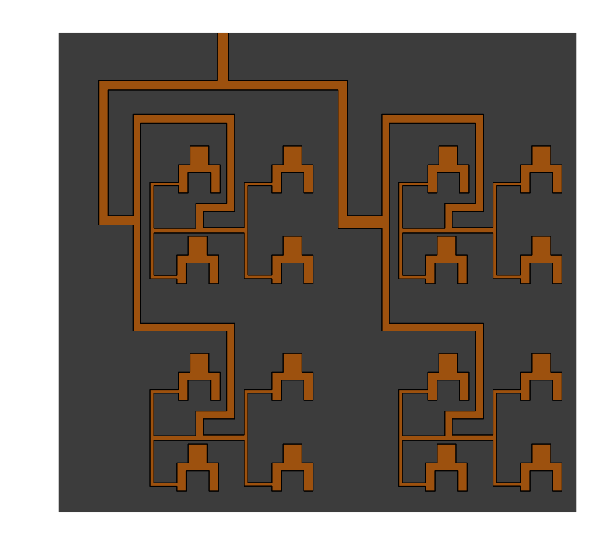
Figure 1 depicts the antenna featuring a square patch with L-shaped slots near the edges, introducing capacitive and inductive effects. This design results in resonant mm-wave frequencies at 28 GHz and 38 GHz. The antenna is simulated using RT/Duroid with specific dielectric properties and is excited through a microstrip feed line. Geometric parameters are imported to enable a parametric workflow, as illustrated in Figure 2.
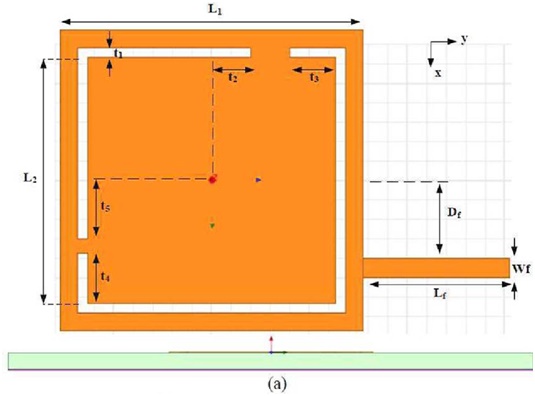
| Variable | Value |
| L1 | 3.1 |
| L2 | 2.5 |
| t1 | 0.1 |
| t2 | 2.7 |
| t3 | 0.4 |
| t4 | 0.4 |
| t5 | 0.5 |
| Lf | 1.5 |
| Wf | 0.2 |
| Df | 0.9 |
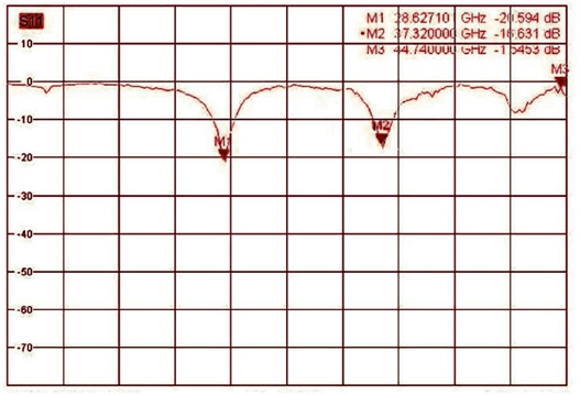
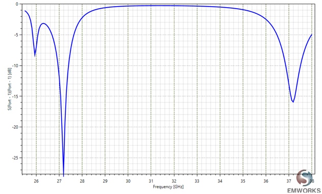
S-Parameters of the 5G antenna
Figure 3 displays the S-Parameters results for the patch antenna, simulated using HFWorks, and the corresponding measured results [2]. The resonant frequencies were identified at 27.375 GHz with a reflection coefficient of -29.87 dB and at 37.125 GHz with a reflection coefficient of -16.39 dB.
Gain of the 5G antenna
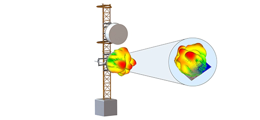
The far-field simulation provides insights into the field distribution around the model at a distance from the structure. Figure 4(a) presents the 3D gain pattern at the first resonance frequency of 27.375 GHz, while Figure 4(b) displays the same gain pattern in a 2D format.
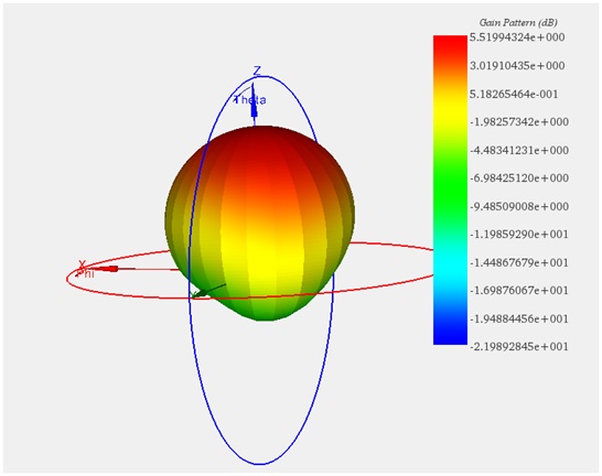
Figure 4-a
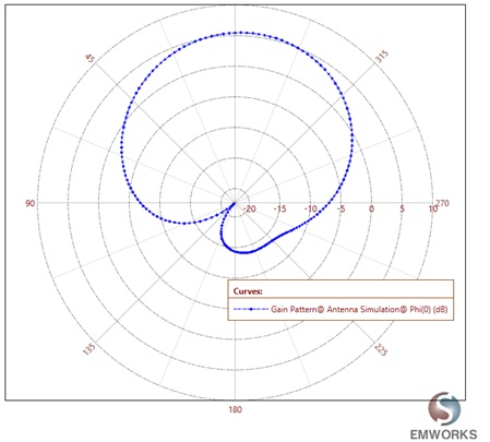
Figure 4-b
Conclusion
This article highlights the application of HFWorks software in designing and simulating a Dual-Band mm-wave antenna for 5G applications, addressing the growing need for high-speed mobile communications. It delves into a 5G antenna model characterized by a square patch with L-shaped slots at the edges, which are instrumental in achieving resonant frequencies at 28 GHz and 38 GHz, crucial for 5G's mm-wave spectrum. The design's geometric parameters are carefully chosen to optimize performance, and the antenna is simulated using specific dielectric materials, ensuring accuracy in the design process. S-Parameter results from HFWorks simulations align closely with measured data, identifying resonant frequencies with significant precision. Furthermore, far-field simulations illustrate the antenna's gain pattern, offering insights into its effective radiation characteristics at these frequencies. This study emphasizes the importance of simulation tools like HFWorks in developing antennas that meet the stringent requirements of 5G wireless communication systems, paving the way for enhanced mobile connectivity. systems.
References
[1] https://www.emworks.com/product/ATLASS
[2] Menna El Shorbagyl, Raed M. Shubair, Mohamed I. AIHajri, Nazih Khaddaj Mallat, ''On the Design of Millimetre-Wave Antennas for 5G '', Microwave Symposium (MMS), 2016 16th Mediterranean, IEEE 2016, pp. 1-4.