Linear Synchronous Motors
The rising demand for linear motors is mainly due to their advantages over traditional mechanical, hydraulic, or pneumatic systems in manufacturing, as well as their application in high-speed transport and elevators. Linear synchronous motors (LSMs) vary in design, including flat or tubular shapes, single or double-sided configurations, slotted or slotless structures, and iron or air cores, with either transverse or longitudinal flux. This note focuses on analyzing a 3-phase double-sided flat LSM motor prototype using EMWorks2D.
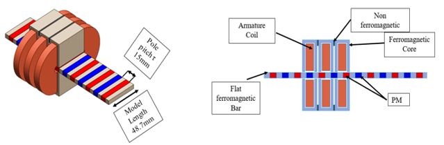
Fig. 1. Flat Slotted Iron Cored Linear Synchronous Motor (FLSM) Model
FLSM Settings
1. Material Selection
The FLSM model utilizes stainless steel 1010 for the core ferromagnetic material and rare-earth sintered NdFeB grade-35 magnets, known for high coercivity and remanence. These materials significantly enhance the motor's performance.
| Motor Component | Material |
|---|---|
| Armature coil | Copper |
| Flat ferromagnetic bar | Stainless steel 1010 |
| Ferromagnetic core | Stainless steel 1010 |
| Permanent magnet (PM) | N35 |
| Non ferromagnetic core | Aluminum |
2. Coercivity Direction and Winding Layout
As shown in Figure 2, the coercivity direction is chosen so that the magnetic flux will be longitudinal from the magnets, the ferromagnetic flat bars will play the role of a magnetic flux conducting material so they will transform the direction of flux to be transversal if a ferromagnetic core is sufficiently close to them.
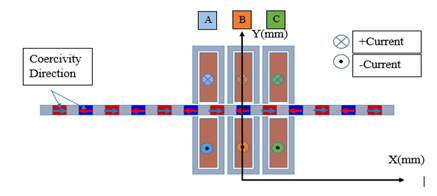
Fig. 2. Coercivity Direction and Winding Layout
3. Defining Distance for Linear Motion
The distance is defined as a mate between the mover (magnets + ferromagnetic bars) and the stationary component, which is in this case the armature (ferromagnetic core + armature winding) as shown in Figure 3.
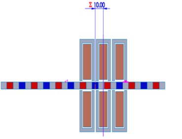
Fig. 3. Distance Definition
Simulation and results
1. Open circuit simulation of FLSM (Detent force and Back EMF)
For an open circuit or no-load simulation in EMWorks2D, set the armature winding to current-driven mode with zero current. The simulation's duration and time step should align to allow the mover to displace by twice the pole pitch, ensuring accurate simulation outcomes.
| Parameter | Value |
|---|---|
| Simulation time | 0.03 s |
| Time step | 0.0005 s |
| Velocity | 1 m/s |
| Distance | 30 mm |
| Initial position | 0 mm |
| Number of turns per phase | 280 |
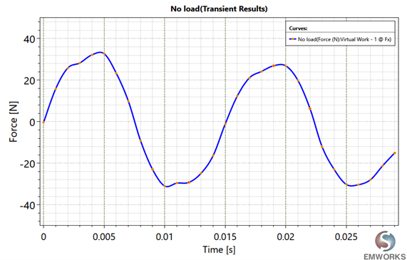
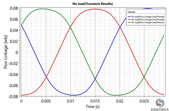
Fig. 5. Flux Linkage
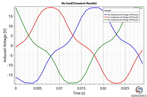
Fig. 6. Induced Voltage
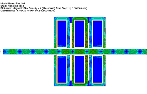
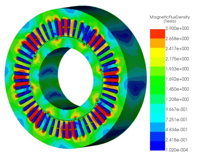
Fig. 7. Flux Density
2. On-load analysis of FLSM (Thrust Values)
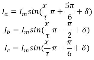
During the on-load test in EMWorks2D, armature winding currents vary based on mover position (x). With a moving range equivalent to 15 mm (one pole pitch) and a peak current of 8 A at a linear velocity of 1 m/s, specific current equations for each phase ensure accurate simulation under load.
Where ![]() is the load angle, to get the maximum thrust, different simulations were performed with
is the load angle, to get the maximum thrust, different simulations were performed with
![]()
Linear velocity depends only on frequency and pole pitch value according to the equation,
![]()
Similarly, the values of the current are obtained at a 33Hz frequency.
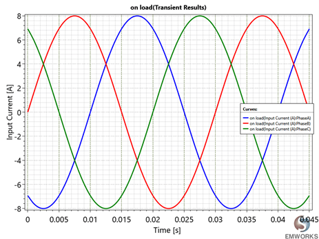
Fig. 8. Input Current Versus Distance
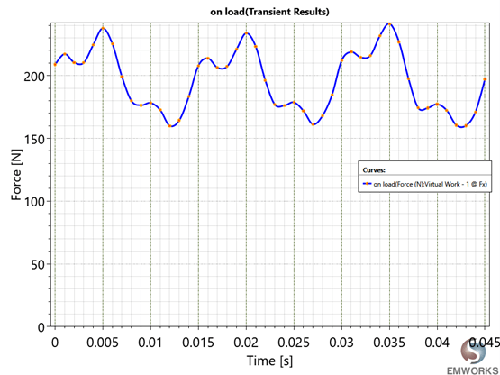
Fig. 9. Thrust
The simulation results obtained are tabulated as shown in Table 3.
| Parameter | Value |
|---|---|
| Maximum force, fmax | 241.34 N |
| Minimum force, fmin | 160.01 N |
| Average force, fav | 196.10 N |
| Force ripple coefficient, kr | 0.414 |
| Maximum detent cogging force | 25.66 N |
The force ripple coefficient is computed as:
![]()
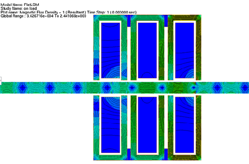
Fig. 10. On- Load Flux Density Plot
3. Dynamic Simulation of FLSM
The FLSM dynamic simulation parameters are shown in Table 4. The armature currents are the same as the on-load simulation and the speed values are computed using the dynamic Newtonian equation
| Parameter | Value |
|---|---|
| Mover mass (kg) | 1 |
| Dumping Factor (N-s/m) | 0.001 |
| Initial velocity (m/s) | 0 |
| Initial position (m) | 0 |
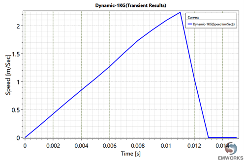
Fig. 11. Dynamic Speed
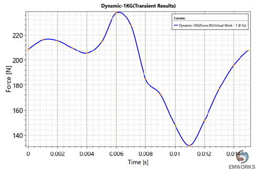
Fig. 12. Dynamic Force
The simulation results obtained are tabulated as shown in Table 5.
| Parameter | Value |
|---|---|
| Maximum force, fmax | 237 N |
| Minimum force, fmin | 132 N |
| Average force, fav | 194.04 N |
| Force ripple coefficient, kr | 0.5411 |
Conclusion
In summary, the application note explores the analysis of Flat Slotted Iron Cored Linear Synchronous Motors (FLSM), driven by their increasing adoption across various industries. The focus is on a 3-phase double-sided flat LSM motor prototype using EMWorks2D. Material selection, coercivity direction, winding layout, and defining distance for linear motion are key considerations. Simulation results from open circuit and on-load analyses provide insights into the motor's behavior, while dynamic simulation parameters deepen understanding of its performance dynamics. This comprehensive analysis offers valuable insights for motor design and optimization, showcasing the effectiveness of EMWorks2D simulation.
Reference
[1] Gieras, Jacek F., Zbigniew J. Piech, and Bronislaw Tomczuk. Linear synchronous motors: transportation and automation systems. CRC press, 2016.