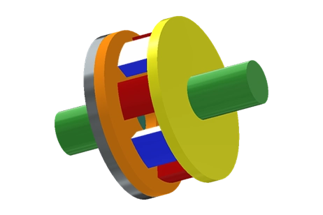
An Axial Flux Permanent Magnet
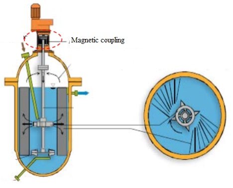
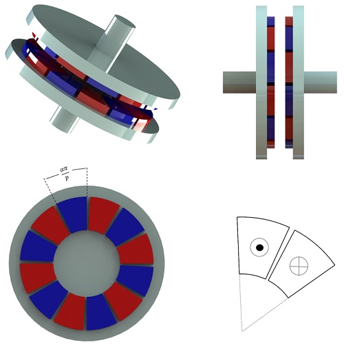
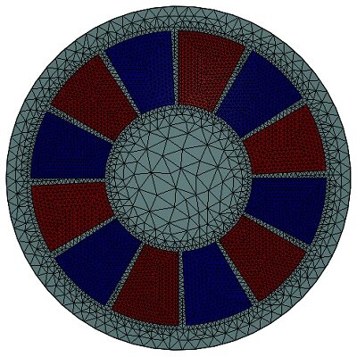
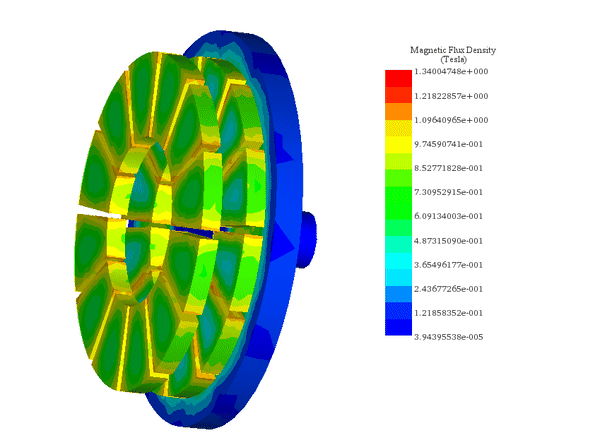
Permanent Magnet (PM) couplings enable contactless torque transmission, ideal for sealed or high-security applications, reducing maintenance and enhancing longevity. These systems, available in axial or radial designs, use alternately magnetized PMs for efficient torque transfer. The study zeroes in on the compact, high-torque axial flux PM coupling, featuring Soft-Iron discs and a configurable air gap for precise torque control. Optimization and performance analysis are conducted through FEM 3D electromagnetic analysis by EMS, focusing on magnet quality, pole number, and air gap distance. Figure 3 depicts the design of the axial flux PM coupling.
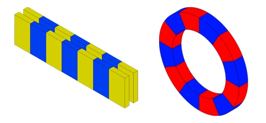
![Topologies of the Radial flux and Axial flux magnetic coupling [1]](/ckfinder/userfiles/images/Topologies-of-the-Radial-flux-and-Axial-flux-magnetic-coupling.jpg)
Problem description
The EMS magnetostatic module leverages parametric studies to forecast how changes in geometry affect field distribution and torque in PM couplings. It examines the magnetic performance by adjusting:
- The mechanical displacement angle between two rotors, keeping the air gap fixed.
- The air gap distance between rotors, maintaining a constant load angle.
Essential geometrical dimensions are specified in Table 1 below:
| Component | Dimensions (mm) |
| Outer radius | 60 |
| Inner radius | 30 |
| Outer yoke radius | 70 |
| Yoke thickness | 10 |
| PM thickness | 7 |
| Air gap thickness | 9.5 |
| Number of pole pairs | 6 |
| Magnet opening to pole-pitch ratio | 0.9 |
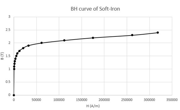
The magnets are axially magnetized and have a relative permeability equal to 1. The ferromagnetic yokes have been chosen with a thickness of 10mm to avoid magnetic saturation and they are made of Soft iron material characterized by the non-linear BH curve figured below.
Table 2 defines the corresponding material properties mentioned above.
| Material | Magnetic permeability | Electrical conductivity $$ \left( \frac{S}{m} \right) $$ | Remanence Coercivity |
| Soft Iron-yoke | BH curve | 10 | - |
PM-NdFeB | 1 | 0 | 1.25 T 994718.4 A/m
|
Parametric study
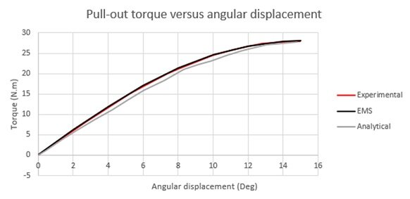
In Case 1, the study varies the mechanical displacement angle between rotors with matching magnetized poles, keeping the air gap at 9.5 mm. This setup allows the calculation of electromagnetic and static torque across different angles, finding the highest static torque at a 15° load angle.
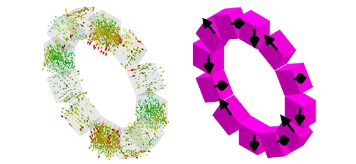
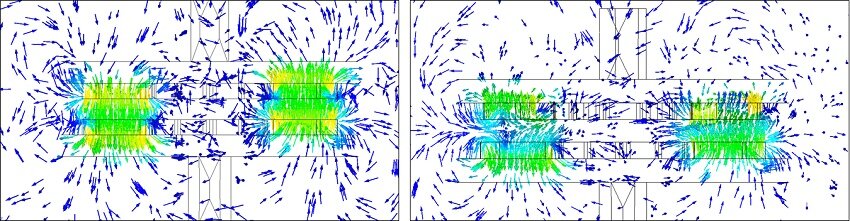
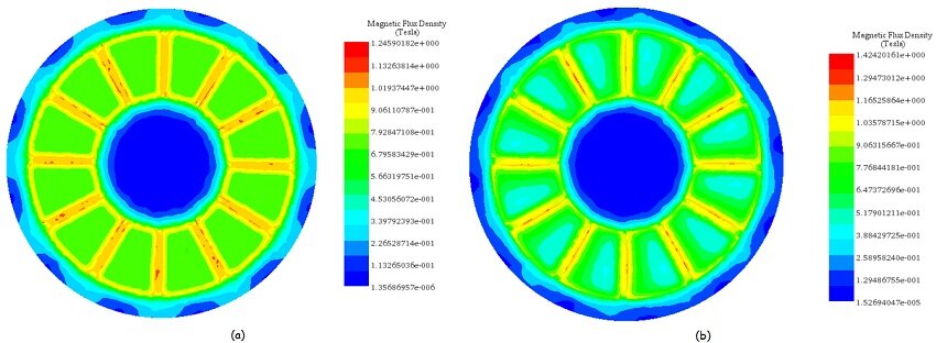
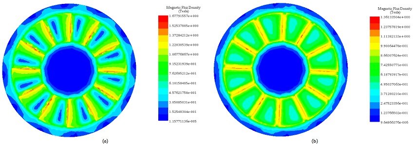
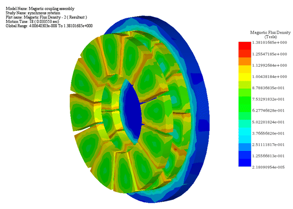
Figures 6-a) and 6-b) illustrate the axial magnetic flux density at coupler angles of 0° and 15°. At 0°, where poles of the same magnetization align, magnetic reluctance and torque are at their lowest. At 15°, magnetic reluctance spikes, maximizing the magnetic torque, highlighting the optimal angle for maximum torque generation.
The following figure confirms the excellent agreement between experimental and EMS FEM simulation results for static torque versus angular displacement, consistent with analytical calculations from Ref [3]. Beyond a 15° angular load, torque decreases until realignment with the next magnetized pole.
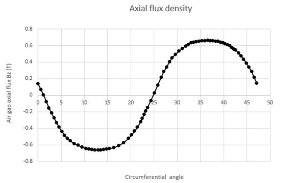
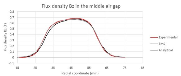
The figure illustrates the flux density distribution along the Z-axis across the central air gap at the pole's midpoint. This distribution is compared with both experimental and analytical results for validation.
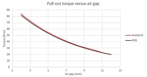
In Case 2 of the parametric study, where the mechanical load angle is held constant at 15°, altering the air gap distance yielded the following results:
The pull-out torque of the magnetic coupling declines sharply as the distance between magnets increases. In our study, the maximum torque almost halves as the air gap widens from 2mm to 7mm, highlighting its significance.
Motion study
In Case 1, with a fixed air gap of 9.5 mm and a constant angular speed of 500 rpm (3000 Deg/s) applied to the mover rotor while the second rotor is fixed, the Motion study within EMS's magnetostatic analysis calculates the torque and angular displacement of the driver rotor over time.
Throughout the 64 ms simulation, the torque (Tz) oscillates between its maximum and minimum values based on the position of the polarized poles relative to each other.
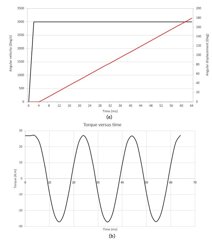
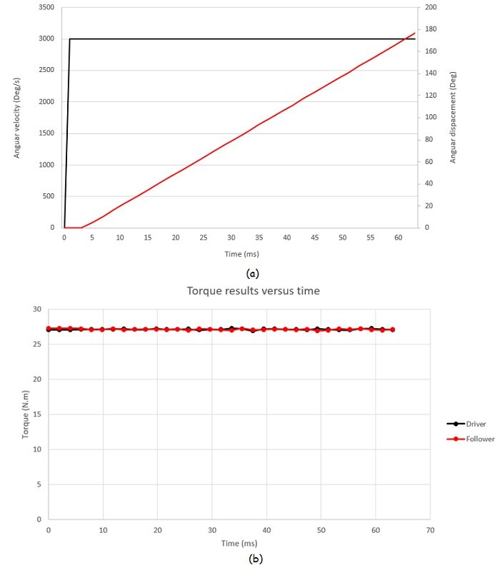
Case 2: For a fixed air gap of 9.5 mm and a constant angular speed of 500 rpm applied to the mover rotor while keeping the load angle of $$ \phi = 15^\circ $$ between the similarly polarized poles: the Motion study coupled to the magnetostatic study of EMS allows to compute the generated torque and speed of the follower rotor versus time.
As a synchronous machine, both rotors rotate at identical speeds and torque levels due to fixed mechanical constraints ensuring a constant angular shift between them.
The first figure depicts the angular velocity and displacement of each rotor over time, while the second illustrates dynamic torque results, with an average value stabilizing around 27 N.m.
Conclusion
The application note delves into the analysis and optimization of an Axial Flux Permanent Magnet (PM) coupling system, using 3D electromagnetic Finite Element Method (FEM) analysis through EMS software. The study focuses on enhancing torque transmission in contactless applications, such as sealed environments, where maintenance reduction and longevity are paramount. By adjusting geometrical parameters like the air gap distance and the mechanical displacement angle between rotors, the analysis explores the magnetic gear's performance, including field distribution and torque generation. The results highlight the axial flux PM coupling's ability to efficiently transfer torque without physical contact, showcasing a detailed examination of magnetic flux density and torque generation at various rotor angles and air gap distances. The findings confirm the direct correlation between these parameters and the system's magnetic performance, with optimal torque achieved at specific load angles and air gap settings. This study underscores the potential of axial flux PM couplings in applications requiring reliable, maintenance-free power transmission, providing a foundation for further exploration and design refinement of magnetic coupling systems.
References
[1] Dolisy, Bastien, et al. "A new analytical torque formula for axial field permanent magnets coupling." IEEE Transactions on Energy Conversion 30.3 (2015): 892-899.
[2] Dolisy, Bastien, et al. "Three-dimensional analytical model for an axial-field magnetic coupling." (2014).
[3] Lubin, Thierry, Smail Mezani, and Abderrezak Rezzoug. "Experimental and theoretical analyses of axial magnetic coupling under steady-state and transient operations." IEEE Transactions on Industrial Electronics 61.8 (2013): 4356-4365.