Marchand Balun
Explore our simulation of a Marchand balun, operational at 2.4 GHz with a 1 GHz bandwidth, verified through S-Parameter analysis in HFWorks. The simulation results highlight the balun's capability for equal power distribution and a 180° phase shift between two outputs.
.jpg)
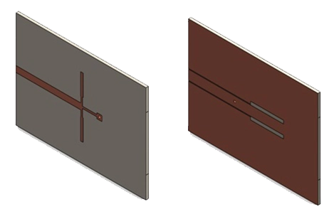
Figure 1: the structure's 3D view in SolidWorks
Simulation
The Scattering Parameters solver excels in analyzing structures by delivering key metrics like Return Loss, Insertion Loss, and Phase Shift between inputs and outputs. Optimal mesh refinement is crucial on conductors, ground slots, and vias to ensure precise frequency response analysis.
Loads/ Restraints
.jpg)
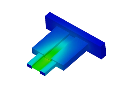
Figure 2: Impedances of the port
Results
.jpg)
Figure 3: Reflection coefficient at the balun’s input port
.jpg)
Figure 4: Insertion losses at the balun’s output ports
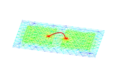
Figure 5: 3D Electric Field Distribution at 3 GHz
Conclusion
This application note explores the simulation of a Marchand balun, designed to operate at 2.4 GHz with a bandwidth of 1 GHz, using HFWorks for S-Parameter analysis. The simulation validates the balun's ability to distribute power equally and achieve a 180° phase shift between its two outputs. The Scattering Parameters solver is utilized to provide essential metrics such as Return Loss, Insertion Loss, and Phase Shift, with careful mesh refinement around conductors, ground slots, and vias to accurately capture the frequency response. The simulation incorporates a zero-thickness conductor on a 0.8 mm RO4003 substrate and models radiation effects with an encompassing air box. Additionally, HFWorks facilitates impedance analysis variations and electric field orientation optimization for precise port mode analysis. The results, including the balun's insertion and return losses across a 1 to 4 GHz frequency range and the 3D electric field distribution at 3 GHz, confirm the accuracy of the HFWorks simulator, aligning closely with actual measurements and demonstrating the effectiveness of virtual prototyping in RF design.
References
[1] A New Planar Marchand Balun Zhen-Yu Zhang, Yong-Xin Guo, L.C. Ong, and M.Y.W. Chia 2005 IEEE