A Double-Sided Permanent Magnet
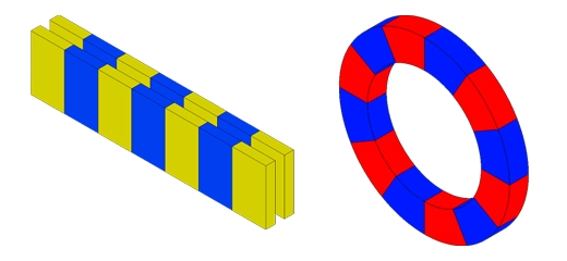
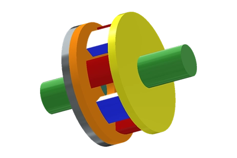
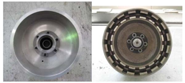
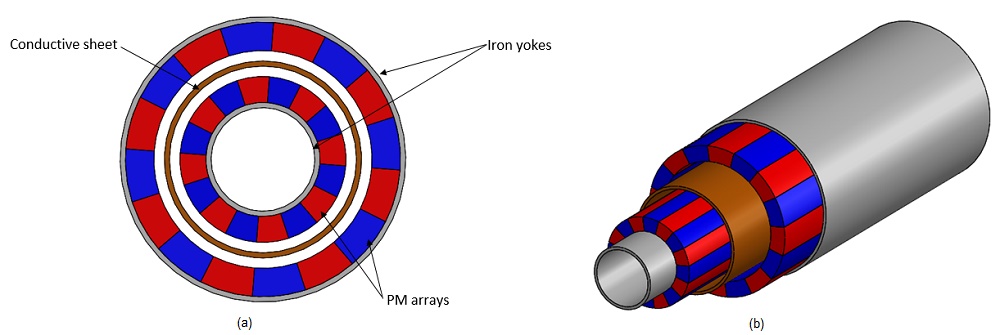
The Eddy current coupler operates on the principle of inducing circular electrical currents within a conductor through a nearby varying magnetic field. Unlike in motors and generators where eddy currents are unwanted, couplers, generate forces facilitating torque transmission without physical contact. This study focuses on the radial type for a Double-Sided Permanent Magnet (DSPM) configuration. Figure 1 depicts the DSPM coupler's real prototype and geometric design, comprising two concentric radially polarized PM arrangements with alternating magnetization directions, supported by inner and outer iron yokes housing a cylindrical conductor sheet.
The materials that are used are summarized in the next table.
| Material | Magnetic permeability | Electrical conductivity (S/m) |
Remanence Coercivity |
| Iron | 4000 | 10 | - |
| PM-NdFeB |
0.823 | 0 | 1.4 T 1353000 A/m |
| Stainless Steel 304 | 1 | 1.37E+6 | - |
Results
The EMS transient magnetic solver was employed to forecast torque and eddy losses when applying an angular speed of 800 rpm to the PM rotors for a simulation duration of 75 ms. The subsequent section presents the transient magnetic simulation with eddy current analysis.
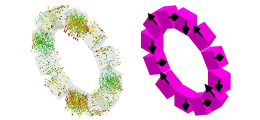
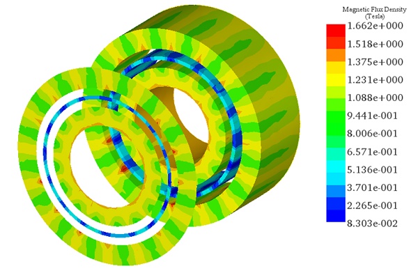
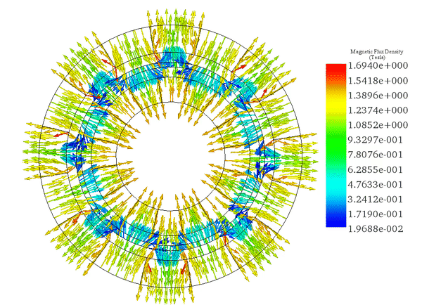
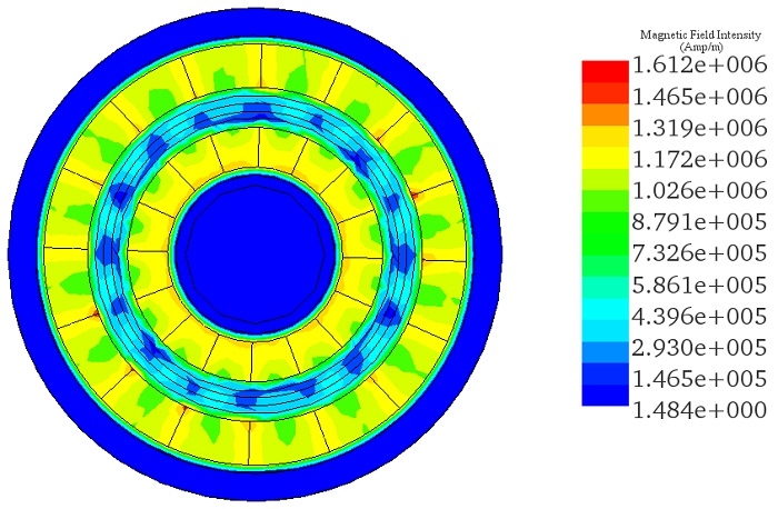
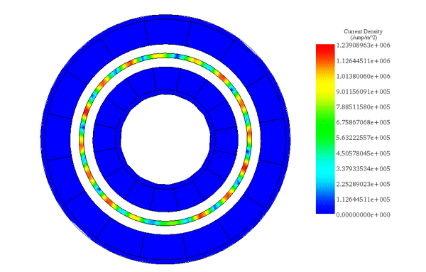
Illustrating the magnetic flux and field density vectors across the coupler, Figures 3a) and 3b) provide insight into the system's behavior. Additionally, Figure 4 showcases the magnetic field intensity at t = 75 milliseconds.
(a)
(b)
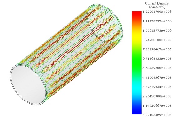
As a result of the moving magnetic field produced by the rotor, eddy currents emerge within the conductor component. The vector plot of these currents across the conductor reveals multiple current loops aligning with each magnet pole and tracing the magnetization directions of the PMs. Despite the constant speed, the eddy currents remain relatively stable throughout the simulation period, as demonstrated in the animation depicted in Figure 5.
(a)
In the initial 2D plot (Figure 6a), the constant angular velocity of the PM rotors is depicted, with a value of 4800 Deg/s. Eddy currents generated within the metallic tube result in an electromagnetic torque that opposes the movement of the PM. The subsequent 2D plot (Figure 6b) illustrates the induced torque versus time, averaging around 58.5E-3 N.m.
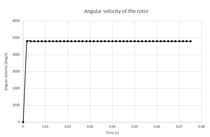
(a)
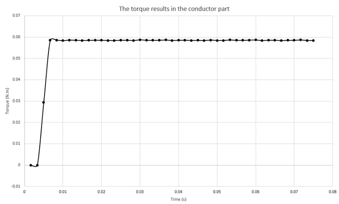
(b)
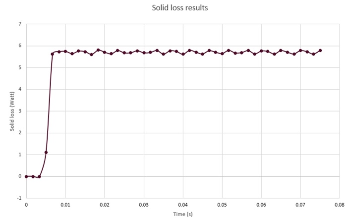
Eddy currents within a metallic surface exhibit two primary aspects: a portion generates an inductive magnetic field, while the remainder dissipates as heat. Eddy loss analysis forecasts the induced solid losses across the conducting part, depicted in the subsequent 2D plot, with an average value of 5.75 W. Figure 7 illustrates the solid loss over time. These results align well with analytical and experimental findings cited in Ref [2], reporting values of 5.98W and 5.9W, respectively.
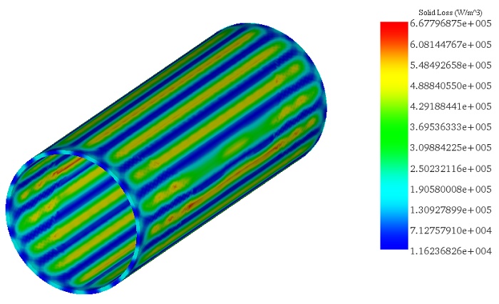
Solid losses predominantly concentrate at the junction of adjacent eddy current loops, as vividly depicted in the subsequent fringe plot (Figure 8) showcasing solid loss density across the conductive part at t=75ms.
Conclusion
This application note delves into the operation and analysis of a Double-Sided Permanent Magnet (DSPM) Eddy Current Coupler, an innovative device utilizing the principle of eddy current induction for torque transmission without physical contact. Through EMS transient magnetic solver simulations, the study investigates the coupler's performance, focusing on torque generation and eddy losses at an angular speed of 800 rpm. The magnetic flux, field density vectors, and the behavior of eddy currents within the cylindrical conductor are meticulously examined, revealing stable current loops that align with the magnetization directions of the concentric radially polarized PM arrangements. The analysis confirms that the coupler generates an electromagnetic torque opposing PM movement, with an average induced torque of 58.5E-3 N.m and average eddy losses of 5.75 W, closely matching analytical and experimental references. Solid losses are identified mainly at the junctions of adjacent current loops, highlighting areas of significant heat dissipation.
References
[1]. Erasmus, Abraham Stephanus. Analytical modelling and design optimization of the Eddy Current Slip Coupler. Diss. Stellenbosch: Stellenbosch University, 2017.
[2] . Zhu, Zina, and Zhuo Meng. "3D analysis of eddy current loss in the permanent magnet coupling." Review of Scientific Instruments 87.7 (2016): 074701.