

Transformer
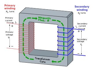
A transformer, an essential static electrical device, facilitates the transfer of electrical energy between multiple circuits via electromagnetic induction. Comprising a core (typically laminated steel), primary, and secondary windings, its operation, as illustrated in Figure 1, hinges on a time-varying current in the primary coil generating a corresponding magnetic field. This magnetic field fluctuation then induces a voltage in the secondary coil, as per Faraday’s law of induction. Crucially, this mechanism enables seamless power transfer between circuits without direct physical contact. But what significance does this hold?
Applications of Transformers
Transformers play a vital role in the electric power sector, primarily used to adjust AC voltage levels as needed. Since the widespread adoption of AC power, transformers have become indispensable in power transmission and distribution. They also feature prominently in the electronic and RF industries, where their size varies greatly. From compact units of a few cubic centimeters for RF applications to massive high-power transformers spanning cubic meters and weighing several tons for interconnecting power grids, their versatility and scalability underscore their significance across various sectors.
Losses in Transformers
Two primary types of losses occur in transformers, crucial for engineering considerations:
1. Core Loss 2. Winding Loss Efficient transformer design aims to minimize these losses. Engineers typically construct a prototype after designing a transformer, then measure losses through open-circuit and short-circuit tests. These tests not only quantify losses but also facilitate the creation of an equivalent circuit for the transformer. With the equivalent circuit established, engineers can seamlessly substitute the transformer with its equivalent circuit, simplifying system-level simulations for further analysis and optimization.
Open Circuit Test
The open circuit test, illustrated in Figure 2, serves to ascertain the core loss within a transformer. As implied, one winding—typically the high-voltage side—is left unloaded. The voltage across the low-voltage winding is then incrementally raised until it matches the rated voltage of the low-voltage circuit. A wattmeter connected to the low-voltage circuit measures the input power, representing the core loss of the transformer.
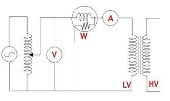
Fig. 2. Open Circuit Test
Short Circuit Test
Figure 3 depicts the connection diagram for the short circuit test. Here, the low-voltage side of the transformer is short-circuited. On the high-voltage side, the voltage is progressively increased until the current attains the rated value for the high-voltage side. The wattmeter reading obtained can be considered an approximation of the copper loss in the transformer. Thus, the short circuit test serves to ascertain the copper loss within the transformer..
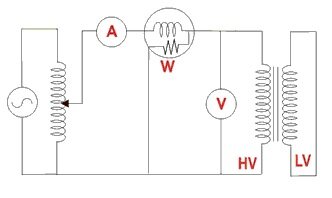
Fig. 3. Short Circuit Test
Open Circuit Test and Short Circuit Test Simulation
The interesting feature about simulation in EMS is the ability to perform both the above-mentioned tests virtually. For the open circuit test, the following inputs are required.
- Material property of the core – the B-H curve of the steel material, lamination details, Core loss curve for the laminate (P-B curve)
- Rated voltage in the Low Voltage side must be applied to the low voltage winding
- The high voltage side must be kept open i.e. a current equal to 0 Amps must be applied to the high voltage winding
Once the simulation is completed, EMS gives the core loss as an output. One can also get the Low Voltage side current from EMS. To perform short circuit test simulation the following inputs are required.
The low voltage side must be shorted. Hence, we apply a 0 voltage across the low voltage winding.
In the high voltage winding we apply different voltages and measure the current till we get the current equal to the rated current in the high voltage side. This can be performed using the Parametric simulation in EMS where the applied voltage can be varied and the current can be measured. Then we take the value of the voltage that gives the rated current and perform the short circuit simulation.
Discussion of Results Including Equivalent Circuit
In this section, I'll provide a concise overview of the EMS modeling process and analyze the results obtained. Figure 4 depicts the model used for simulation, while Figure 5 illustrates the laminate material utilized. Inside EMS, the coil definition is visualized in Figure 6. Results from both the open and short circuit simulations are examined, with each test conducted as a separate study in EMS. Figure 7 displays the Result table, and Figure 8 showcases the section plot of the magnetic flux density during the open circuit test.
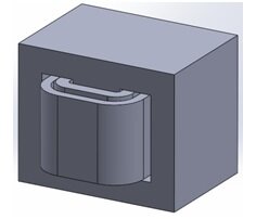
Fig. 4. Single-Phase Transformer Simulated in EMS
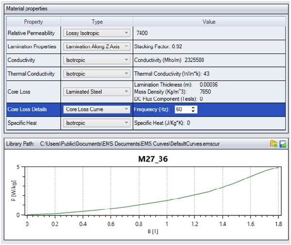

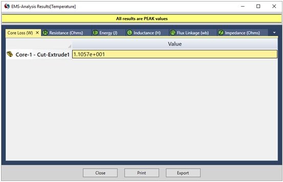

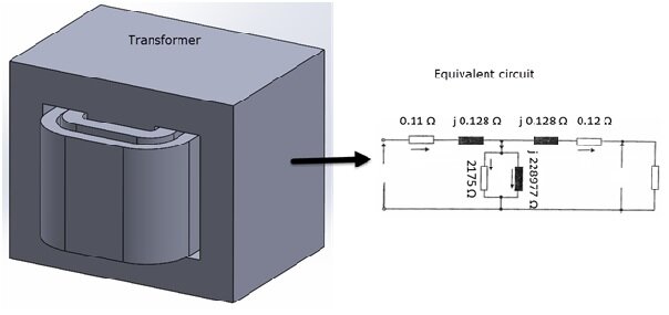
Fig. 9. Equivalent Circuit of the Transformer
Conclusion
In conclusion, understanding and simulating transformer behavior are crucial for enhancing efficiency in power transmission systems. With EMS, engineers can effectively model transformer operations, analyze performance factors, and optimize designs for maximum efficacy. By delving into the intricacies of transformer simulation and leveraging EMS capabilities, engineers can unlock insights that lead to more robust and efficient power distribution networks. With this comprehensive approach, the journey towards optimizing transformer performance becomes streamlined and effective, ensuring reliable and sustainable power supply systems for diverse applications.
Watch our Webinar on Transformer Simulation
To watch EMS in action and see how to simulate both open and short circuit studies in EMS click below to watch our webinar on transformer.