

Even a beautifully modeled design can fall apart when it's time to simulate. That’s because CAD models made for manufacturing or visualization often contain details or flaws that derail electromagnetic (EM) analysis. In this part of the series, we highlight the most common geometry issues that silently compromise simulation accuracy and stability—and why fixing them early matters.
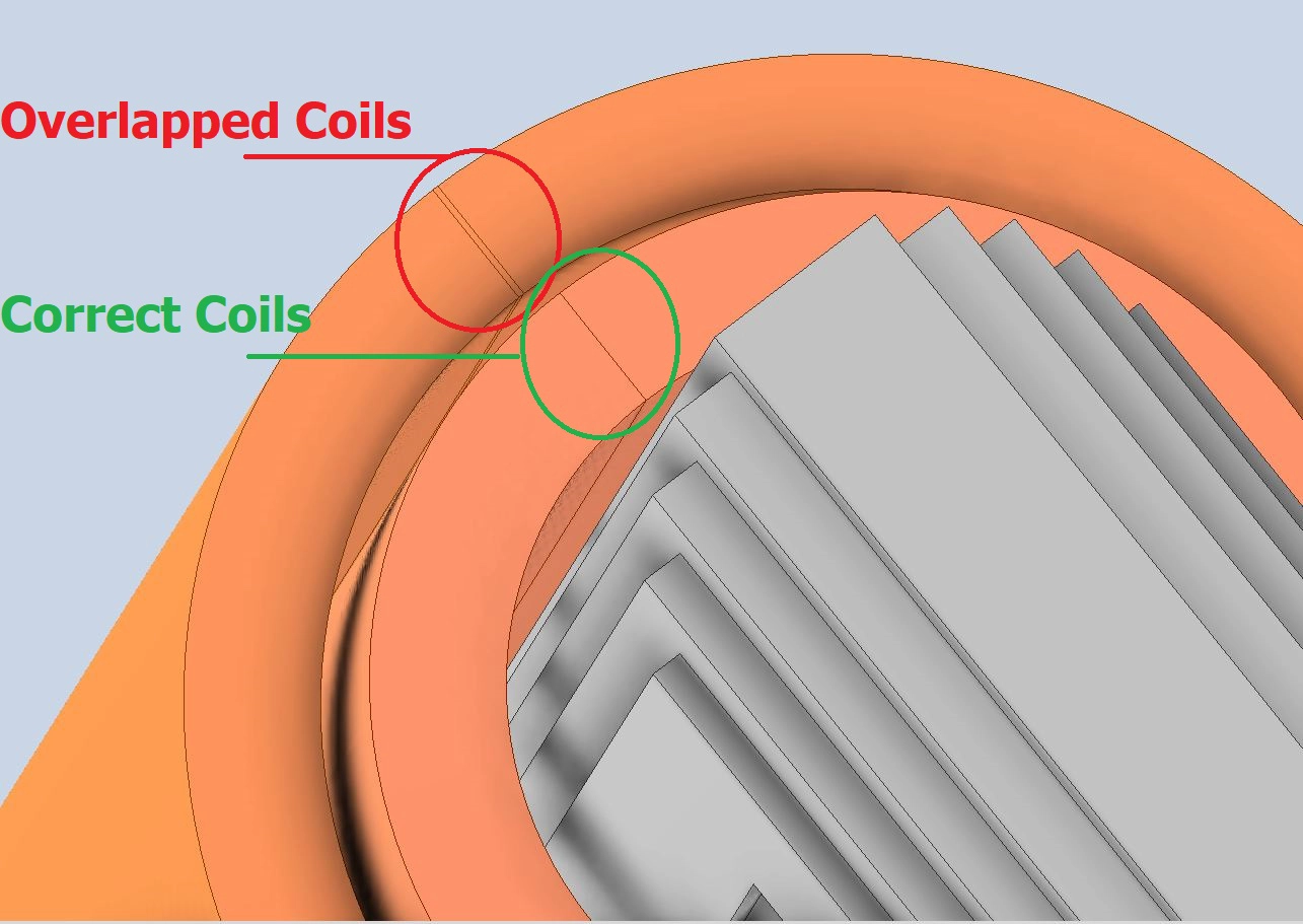
Gaps and Overlaps: The Silent Simulation Killers
Gaps are unintended spaces between surfaces that should be touching. Overlaps are geometry errors where solids intersect or occupy the same space.
Why it matters
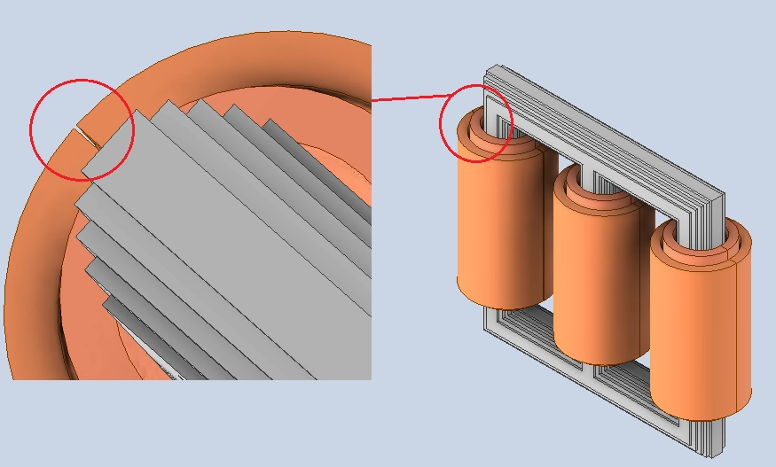
A small gap in a conductive path can break the simulated current flow.
Overlapping parts confuse solvers about material boundaries, causing failed or inaccurate meshing.
Fix it: Use CAD healing tools to close gaps, eliminate duplicates, and create watertight geometry.
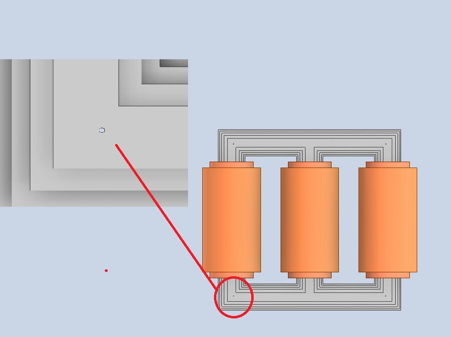
Tiny Features That Don’t Matter Physically—but Break the Mesh
Screw holes, embossed logos, and tiny fillets often have no significant EM effect, yet force the mesher to create thousands of unnecessary small elements.
Why it matters
These features increase mesh size and simulation time.
They may destabilize the solver due to poor aspect ratios or tiny time steps.
Fix it: De-feature the model. Remove or suppress anything that doesn’t influence electromagnetic behavior at the frequencies of interest.
Non-Manifold Geometry: Looks Fine, Fails Fast
Non-manifold edges and faces are those that don’t form valid 3D solids—like an edge shared by three surfaces or a face with no thickness.
Why it matters
These errors confuse the mesh generator and can’t be interpreted as real-world objects.
They often lead to mesh failures or invalid physics regions.
Fix it: Run a “manifold check” in your CAD or preprocessing tool. Clean up any edge or face that isn’t part of a consistent volume.
Disconnected or Misaligned Solids
CAD assemblies often look visually correct but aren’t physically joined. Solids may be misaligned by microns or not share a common interface.
Why it matters
Solvers treat them as separate volumes.
You get false field behavior (like unexpected impedance or open circuits).
Fix it: Use Boolean operations or imprinting tools to properly unite or align components.
Why These Issues Are So Common—And So Costly
Many engineers use the same CAD model for both manufacturing and simulation. But simulation requires different priorities: fewer unnecessary details, more attention to continuity, and physically meaningful topology.
Even one overlooked error can throw off results or delay analysis.
EMWORKS, like any EM solver, performs best with well-prepared geometry. Addressing these issues up front leads to smoother setup, faster runs, and more trustworthy field results.
EMWorks software allows users to work seamlessly on a specific design and make geometry changes directly within the CAD environment—without needing to create copies or restart the software. With a single click, the model is updated and remains within the same project, enabling a smooth workflow. This feature is especially valuable in two cases: for small adjustments, users can quickly modify the geometry, re-run the simulation, and make informed decisions; and for large models, only the modified parts require redefinition of simulation inputs, while settings for unaltered components are preserved—significantly saving time and effort.

Best Practices for Long-Term Success
- Clean up geometry: try to simplify the model by selecting the parts that impact or be impacted by the simulation to optimize the computation time.
- In case of geometry design errors, such as having interference, open loops, zero bodies etc.., the software is intuitive and provides guidance by showing alerts where the error occurred.
- The software is open to simulation any model with variant dimensions by providing both automatic mesh and mesh control feature that offers more flexibility for users to refine or coarsen the mesh in specific regions.
- In case the user needs to modify the geometry, he can simply use the update geometry option which allows him to save time and work in the same interface without the need to make copies or close the interface. With a simple click the model will be adjusted and he can enter the settings and get the updated results.
- Try to save the model at each important step. However, in the event of critical issues the software provides the “restore” feature that allows you to recover the simulation files.
- Don’t wait until the end: Clean up geometry early and incrementally during design.
- Automate where possible: Use CAD/CAE tools for healing, defeaturing, and validation.
- Use a checklist: Document each cleanup step so geometry changes are traceable.
- Keep units and tolerances consistent: Scale errors and misaligned tolerances are common and costly.
- Work on a simulation copy: This preserves the production model while optimizing the simulation version.