Switched Reluctance Motor (SRM)
Switched reluctance motors (SRMs) are distinguished by their simple, robust structure and lack of rotor windings or permanent magnets, making them ideal for high-speed applications. Their high power density is particularly beneficial for electric vehicle traction motors, positioning high-speed SRMs as promising options for enhancing efficiency and performance in the EV industry.
CAD model of a Switched Reluctance Motor
The designed switched reluctance motor is characterized as a three-phase machine, featuring six inner stator poles, eight outer rotor poles, and a shaft, as depicted in Figure 1.
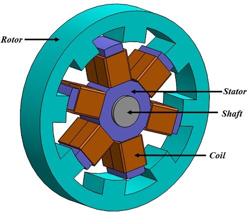
Figure 1 - 3D model of a switched reluctance motor
EMS Simulation of the In-Wheel Switched Reluctance Motor
In EMS, switched reluctance motors undergo analysis via Transient Magnetic simulations coupled with motion, focusing on time-domain magnetic fields. This method computes key quantities like magnetic flux density (B), magnetic field (H), and current distribution (J), alongside derived metrics such as forces, torques, and losses. The simulation parameters were set to a Start Time of 0 s, End Time of 0.24 s, and Time Increment of 0.0025 s for detailed evaluation.
EMS study coupled to CAD
In the simulation, the rotor and shaft move within an Air region, driven by electromagnetic force from activated coils. At each time step, torque values from EMS update their positions. This process, facilitated without specifying software, ensures accurate motion dynamics. The motion is controlled by dynamic torque values provided by EMS, with no explicit mention of software tools.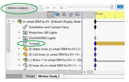 Figure 3 - Preparing the Motion study in SolidWorks
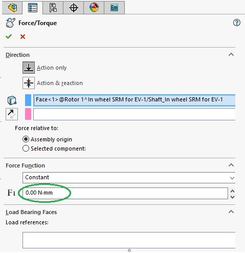 Figure 4 - Torque definition in Motion study
In EMS, a virtual work is established at the origin of the rotor and shaft, linked to the torque specified in the motion study. This coupling enables a comprehensive motion analysis within the EMS framework, integrating transient magnetic studies seamlessly with motion simulations.
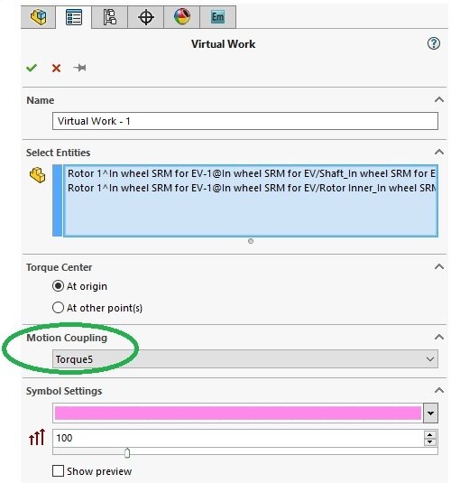 Figure 5 - Virtual Work definition in EMS
Coils
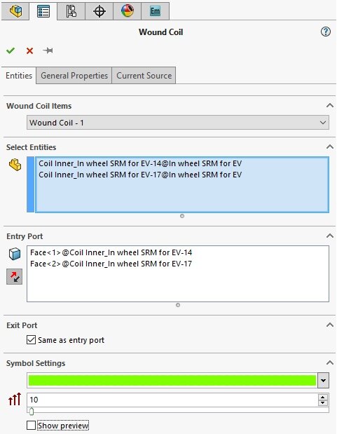
Figure 7a - Wound coil definition in EMS by entities
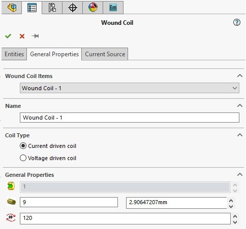
Figure 7b - Wound coil definition in EMS
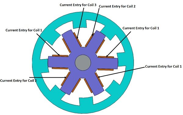 Figure 8 - Current entry ports for the three wound coils
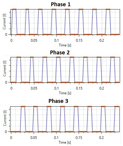
Figure 9 - Current excitation of the three phases
Material
The simulated model comprises a stator, rotor, shaft, coils, Inner Air, Band, and Outer Air. Table 1 summarizes the material properties used in the model.
Table 1: Materials used in the EMS simulation
| Component | Material | Relative permeability | Conductivity (S/m) |
| Stator, rotor, shaft | M-19 | Nonlinear | 0 |
| Coils | Copper | 0.99991 | 5.8e+007 |
| Band, Inner Air, Outer Air | Air | 1 | 0 |
Magnetic flux density computation
| Parameter | EMS result | Reference[1] result |
| Magnetic flux density maximum value | 2.11 Tesla | 1.9 Tesla |
3D fields generated by the Switched Reluctance Motor
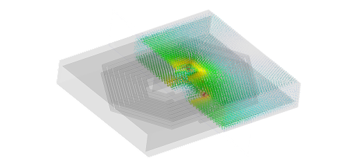
EMS produces 3D plots illustrating the magnetic flux density. Figure 10 displays the 3D vector plot, while Figure 11 depicts the 3D plot of the magnetic flux density.
 Figure 10 - 3D Vector plot of magnetic flux density
Figure 11 - 3D plot of the magnetic flux density
Conclusion
EMS simulation offers invaluable insights for optimizing switched reluctance motors (SRMs) in electric vehicles, enhancing efficiency and performance. By accurately modeling electromagnetic phenomena and motion dynamics, EMS empowers engineers to design high-speed SRMs with improved power density and reliability. With EMS, electric vehicle manufacturers can accelerate innovation in motor technology, driving the transition towards sustainable transportation. Explore the potential of EMS simulation for SRMs and other electric vehicle components to revolutionize the automotive industry.