

Simulation of BLDC motor
This article presents the creation and simulation of a BLDC motor using EMWorks2D and MotorWizard (Figure 1). The BLDC model, discussed in [3], is automatically generated via MotorWizard, an electric motor software by EMWorks. Alongside MotorWizard, EMWorks offers EMWorks2D, a 2D electromagnetic software employing the finite element method (FEM).
FEM simulation effectively analyzes complex electromagnetic problems and geometries [3], aiding in electric machine design by accommodating geometry, material behavior, and winding distribution. While 3D solutions offer comprehensive results, they require more time and resources. For tasks like machine design or fault analysis, the 2D approach provides faster computation and satisfactory results, facilitating the development of efficient motors.
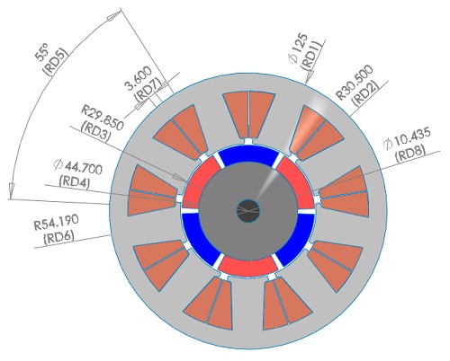
Figure 1 depicts the 2D geometry of the simulated BLDC motor, featuring a 3-phase machine with 12 slots and 6 poles. The motor's symmetry angle is Θ = 120° mechanical degrees. Both the stator and rotor cores are constructed from steel (μ_r = 1000). Ferrite permanent magnets (Br = 0.4 T) compose the rotor poles, arranged in a surface-mounted structure. Additionally, the shaft comprises non-magnetic material. The windings consist of double layers distributed across the 3 phases, each with a coil pitch of 1 and 1456 turns per phase.
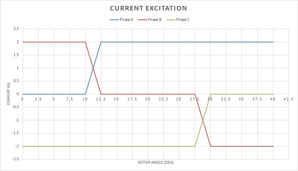
The excitation signal for each phase is represented by three ideal square-wave currents. The three-phase winding is connected in a wye configuration. However, at any given position, only two phases receive power while the third remains unexcited. The switching between phases, determined by the rotor position, occurs every 360 electrical degrees of rotation.
As eddy effects and iron losses are disregarded in this simulation, a static magnetic analysis is conducted. A parametric sweep study is defined to analyze both currents and rotor positions, aiming to compute output torque and magnetic flux. Additionally, inductance and flux linkage results will be generated. These torque outcomes will be cross-referenced with those in ref [3].
Meshing step
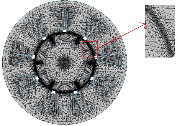
The meshing process is pivotal in FEM simulations. While smaller element sizes improve accuracy, they can prolong computation time. EMWorks2D features a user-friendly mesher with flexible mesh control options for sensitive areas. Figure 3 illustrates the meshed model with applied mesh control in the air gap, showcasing the software's capabilities in optimizing mesh for accurate results.
Results and discussions
The simulation runs across various rotor positions, yielding results. Figures 4a) and 4b) display magnetic flux density in the machine at the initial position (0 deg, with coil A not excited). The flux density patterns, depicted in fringe and vector plots, show flux flowing into and out of the machine center, resulting from the opposite polarity of phases B and C being excited. Particularly, high flux density concentrations are observed at the corners of the stator teeth.
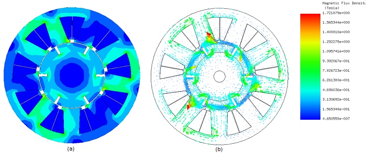
Figure 5 presents an animated plot showcasing the magnetic flux lines in relation to the rotor angle. Additionally, Figure 6 displays contour lines of the magnetic vector potential. These visualizations reveal that the majority of the magnetic field circulates within the motor.
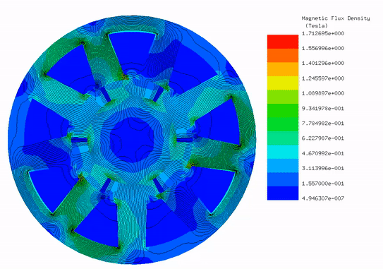
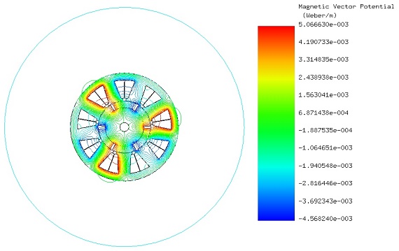
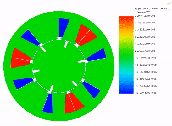
Figure 7 features an animation depicting the applied current density at various rotor positions. Essentially, it showcases the excitation of the three phases at different rotor angles. This commutation strategy aims to maximize torque output while minimizing torque ripple.
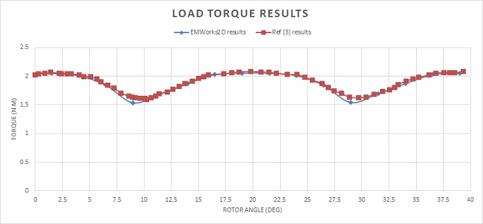
The figure below illustrates the load torque results computed by EMWorks2D over an angle range from 0 degrees to 40 degrees, compared with the findings in [3]. The torque curve exhibits small ripple amplitudes but a significant number of ripples, totaling 18 in one full revolution. The maximum and minimum torque values are 2.05 Nm and 1.53 Nm, respectively, with an average torque of approximately 1.89 Nm.
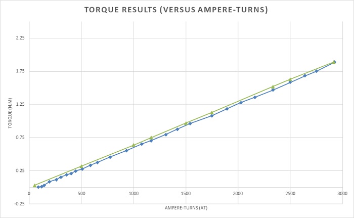
Figure 9 displays the static torque curve (average produced torque) plotted against ampere-turns, indicating a proportional relationship. At zero excitation, the torque is around 0.1 Nm (Cogging torque), increasing to an average of 1.89 Nm at 2916 A-t. This linear dependency underscores a notable advantage of the BLDC motor, akin to brushed DC motors, without necessitating commutators and brushes.
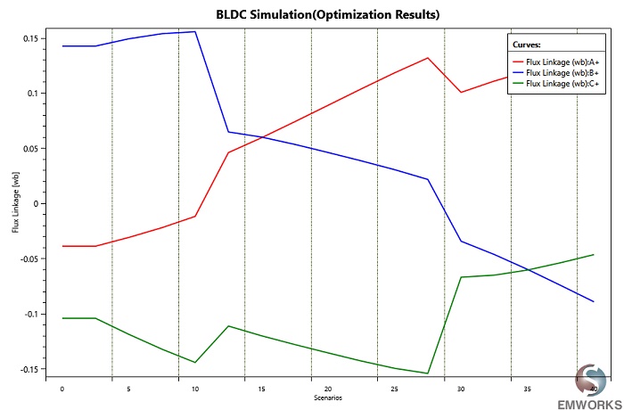
Table 1 summarizes the inductance results of the motor phases, indicating uniform values across all phases. Additionally, Figure 10 depicts the flux linkage results of the three-phase windings.
| Phase A, B and C | |
| Self-inductance (H) | 0.64085 |
| Mutual inductance (H) | 0.61795 |
References
[1]: https://www.iea.org/gevo2018/
[2]: https://www.cnbc.com/2018/05/30/electric-vehicles-will-grow-from-3-million-to-125-million-by-2030-iea.html
[3]: G. M’boungui, E. K. Appiah, A. A. Jimoh, T. R. Ayodele. Simple Numerical Two-Dimensional Magnetostatic Analysis of a Fractional Slot Winding Brushless DC Motor. Proceedings of the World Congress on Engineering and Computer Science 2013 Vol I
WCECS 2013, 23-25 October, 2013, San Francisco, USA