

Introduction
Bluetooth and wireless internet have become integral to modern communication, facilitating streaming on devices like Roku and Apple TV. They're also fundamental to security appliances. Yet, why hasn't wireless charging for batteries become commonplace? Surprisingly, the concept isn't new—it's based on Inductive Charging, which allows for cordless power transfer.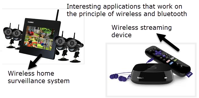
Figure 1 – Many modern day appliances work on the principle of wireless communication
Principle of Inductive Charging
Consider two coils: a transmitter coil that carries a high-frequency AC current, and a receiver coil positioned a short distance away. Despite not being directly excited, the receiver coil develops an induced current via induction, capable of charging devices like cell phone batteries. This system, effective at close range, utilizes the transmitter coil, also known as the Power Transmitter. For long-distance wireless power transfer, the setup shifts to using transmitting and receiving antennas, replacing the coils.
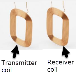
Figure 2 – Wireless charging based on the principle of Induction
What is of interest to engineers?
Engineers designing near-field wireless charging devices concentrate on coil design, transfer efficiency, electrical characteristics like inductance and coupling, and minimizing ohmic losses that heat the coils. To assist in their design and validation, they use an electro-thermal-motion simulation tool. For analyzing far-field wireless power transfer antennas, a different specialized product is employed.
Model setup
The assembly file is crafted based on the specified dimensions of the transmitter and receiver coils, with a separation distance of approximately 3 mm between them.| Coil type | Wire | Dia (out) | Dia (inner) | No of turns | No of layers | |
| Transmitter coil | Planar circular coil | AWG 18 | 42.61 mm | 20.81 mm | 10 | Single |
| Receiver coil | Planar spiral coil | AWG 15 | 19 mm | 6 mm | 5 | Single |
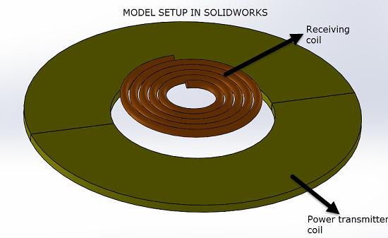
Figure 3 – SOLIDWORKS model of the transmitter and receiver coil
Simulation objectives
Using EMS, the goal is to determine the inductance of the coils, the coupling coefficient between them, ohmic losses within the coils, the induced voltage in the receiving coil, and the magnetic field they generate. To assess how the coupling coefficient varies with the distance between the coils, a parametric study in EMS will automatically calculate all these parameters across different coil positions.Simulation results
Inductance
The table gives the self, mutual and leakage inductance as calculated by EMS.| Self Inductance (mH) | Mutual Inductance (mH) | Leakage Inductance (mH) | |
| Transmitting coil | 3.38 mH | 0.21 mH | 2.65 mH |
| Receiving coil | 0.27 mH | 0.21 mH | 0.212 mH |
Coupling coefficient and efficiency of the charging device
The EMS calculation reveals a coupling coefficient of 0.22, indicating that 22% of the flux generated by the transmitting coil intersects the receiving coil. The efficiency, defined as the ratio of collected to input energy, stands at approximately 73.5% for this setup. As the distance between the coils increases, efficiency decreases. Efficiency also fluctuates with the frequency of the input signal. Therefore, using EMS in conjunction with design software enables the prediction of the optimal distance and excitation level for the transmitting coil to achieve maximum power transfer.Power and Efficiency
| Input Power (mW) | Output Power (mW) | Induced Voltage (mV) | |
| Transmitting coil | 3.8 mW | ||
| Receiving coil | 2.78 mW | 82 mV |
3D plots
The figures below show plots of Magnetic flux density and Current density. EMS can help you visualize results inside your geometry and get a good understanding of what is going on.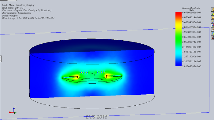
Figure 4 – Section plot of the magnetic flux density created with the power transmitter
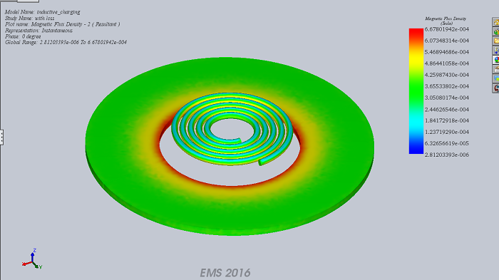
Figure 5 – Magnetic flux density on the coils
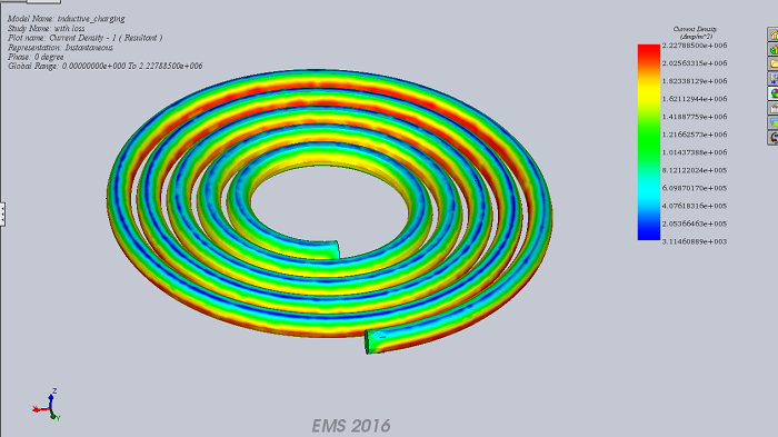
Figure 6 – Current density plot on the receiver coil
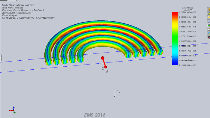
Figure 7 - Section of the current density to see how the current is distributed inside the cross-section
Wireless charging, leveraging inductive charging principles, represents a pivotal shift towards more convenient and advanced power solutions. This application note delves into the intricacies of optimizing coil design and electrical characteristics to improve efficiency and reduce losses, a crucial endeavor for engineers. With the aid of specialized simulation tools, the potential for refined and efficient wireless charging systems is vast, promising significant advancements in how we power our devices. This exploration not only answers fundamental questions about wireless charging's workings but also guides the optimization process for better performance and integration into our daily lives.