3 phase high voltage submarine power cables and their impact on marine ecosystem – How EM Simulation can help engineers design eco-friendly power transmission cables

high power Power Cables
By Majdi EL Fahem | 08/06/2017

About submarine cables

A submarine power cable is a major transmission cable for carrying electric power below the surface of the water. These are called "submarine" because they usually carry electric power beneath salt water (arms of the ocean, seas, straits, etc.) but it is also possible to use submarine power cables beneath fresh water (large lakes and rivers). Examples of the latter exist that connect the mainland with large islands in the St. Lawrence River. The purpose of submarine power cables is to transport electric current at high voltage. The electric core is a concentric assembly of inner conductor, electric insulation and protective layers. The conductor is made from copper or aluminum wires, the latter material having a small but increasing market share. Conductor sizes ≤ 1200 mm2 are most common, but sizes ≥ 2400 mm2 have been made occasionally. For voltages ≥ 12 kV the conductors are round. Three different types of electric insulation around the conductor are mainly used today. Cross-linked polyethylene (XLPE) is used for voltages up to 420 kV. It is produced by extrusion in insulation thickness of up to about 30 mm. 36 kV class cables have only 5.5 – 8 mm insulation thickness. The entire cable core is impregnated with a low-viscosity insulation fluid (mineral oil or synthetic). A central oil channel in the conductor facilitates oil flow when the cable gets warm but this is rarely used in submarine cables due to oil pollution risk at cable damage. Mass-impregnated cables have also a paper-lapped insulation but the impregnation compound is highly viscous and does not exit when the cable is damaged. MI insulation can be used for massive HVDC cables up to 525 kV. Cables ≥ 52 kV are equipped with an extruded lead sheath to prevent water intrusion. No other materials have been accepted so far. The lead alloy is extruded onto the insulation in long lengths (over 50 km is possible). In this stage, the product is called cable core. In single-core cables the core is surrounded by a concentric armoring. In three-core cables, three cable cores are laid-up in a spiral configuration before the armoring is applied. The armouring consists most often of steel wires, soaked in bitumen for corrosion protection. Since the alternating magnetic field in ac cables causes losses in the armoring, those cables are sometimes equipped with non-magnetic metallic materials (stainless steel, copper, brass). Modern three-core cables, e.g. for the interconnection of offshore wind turbines, carry often optical fibers for data transmission or temperature measurement. Cables are typically buried 1 m and exceptionally up to 10 m beneath the seabed to protect against trawl fishing, anchoring and other activities. The speed of burial is around 0.2km/h and is dependent on cable type and seabed conditions. Burial is not always possible, especially in rocky areas. Figure 1 shows the cross section of a 3-phase submarine cable. Figure 2 shows a typical submarine power cable system.   cross section of a 3-phase submarine cables

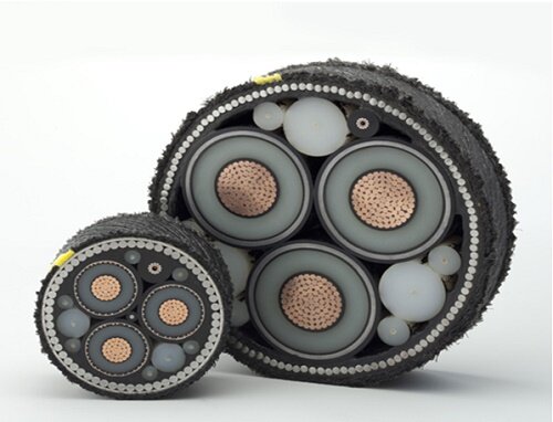
Figure 1 - cross section of a 3-phase submarine cable

Typical submarine power cable system

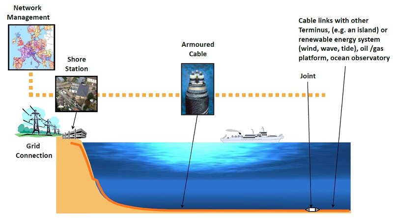
Figure 2 - Typical submarine power cable system


Which is better - AC or DC power transmission?

Most power systems use alternating current (AC). This is due mostly to the ease with which AC voltages may be stepped up and down, by means of a transformer. When the voltage is stepped up, current through the line is reduced, and since resistive losses in the line are proportional to the square of the current, stepping up the voltage significantly reduces the resistive line losses. DC power transmission, which is slowly gaining appeal does have some advantages over AC power transmission. AC transmission lines need to be designed to handle the peak voltage of the AC sine wave. However, since AC is a sine wave, the effective power that can be transmitted through the line is related to the root mean squared (RMS) value of the voltage, which for a sine wave is only (1/sqrt (2)) or about 0.7 times the peak value. This means that for the same size wire and same insulation on standoffs and other equipment, a DC line can carry sqrt (2) or just over 1.4 times as much power as an AC line. AC power transmission also suffers from reactive losses, due to the natural capacitance and inductive properties of wire. DC transmission lines do not suffer reactive losses. The only losses in a DC transmission line are the resistive losses, which are present in AC lines as well. For an overall power transmission system, this means that for a given amount of power, AC requires more expensive wire, insulators, and towers but less expensive equipment like transformers and switch gear on either end of the line. For shorter distances, the cost of the equipment outweighs the savings in the cost of the transmission line. Over longer distances, the cost differential in the line starts to become more significant, which makes high-voltage direct current (HVDC) economically advantageous. For underwater transmission systems, the line losses due to capacitance are much greater, which makes HVDC economically advantageous at a much shorter distance than on land. Having said that, most submarine cables are still AC systems.

AC subsea cables

Alternating-current (AC) submarine cable systems for transmitting lower amounts of three-phase electric power can be constructed with three-core cables in which all three insulated conductors are placed into a single underwater cable. Most offshore-to-shore wind-farm cables are constructed this way. For larger amounts of transmitted power, the AC systems are composed of three separate single-core underwater cables, each containing just one insulated conductor and carrying one phase of the three-phase electric current. A fourth identical cable is often added in parallel with the other three, simply as a spare in case one of the three primary cables is damaged and needs to be replaced. This damage can happen, for example, from a ship's anchor carelessly dropped onto it. The fourth cable can substitute for any one of the other three, given the proper electrical switching system. Below in table 1 we find some examples of installed AC submarine cables.
Connecting Connecting Voltage
Tarifa, Spain (Spain-Morocco Interconnection) Fardioua, Morocco through the Strait of Gibraltar 400 kV
Mainland Sweden Bornholm Island, Denmark  60 kV
Wolfe Island, Canada Kingston, Canada 245 kV

Table 1 - Examples of AC submarine cables

Applications

  • Historically, submarine power cables linked shore-based power grids across bays, estuaries, rivers, straits, etc.
  • Now submarine cables carry power between countries and to offshore installations, e.g. oil/gas platforms and ocean science observatories.
  • Submarine cables also transfer power from offshore renewable energy schemes to shore, e.g. wind, wave and tidal systems.
Offshore wind farm in UK

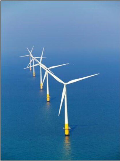
Figure 3 - Offshore wind farm in UK

Offshore oil platform with power supply through a submarine cable

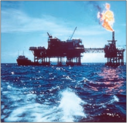
Figure 4 - Offshore oil platform with power supply through a submarine cable

Power cables EM radiation and environment

Electromagnetic fields are generated by operational AC transmission subsea cables. Electric fields increase in strength as voltage increases and may be as strong as 1000 µV per m. In addition, induced electric fields are generated by the interaction between the magnetic field around a submarine cable and the ambient saltwater. Magnetic fields are generated by the flow of current and increases in strength as current increases. This strength may sometimes exceed the natural terrestrial magnetic field. Magnetic fields are best limited by appropriate technical design of the cable (for example, three-phase AC). Directly generated electric fields are controllable by adequate shielding, however, induced electric fields generated by the magnetic field will occur. Because the strength of both magnetic and electric fields rapidly declines as a function of the distance from the cable, an additional reduction of the exposure of marine species to electromagnetic fields can be achieved by cable burial. Magnetic fields generated by cables may impair the orientation of fish and marine mammals and affect migratory behaviour. Field studies on fish provided first evidence that operating cables change migration and behaviour of marine animals (Klaustrup, 2006). Marine fish use the earth’s magnetic field and field anomalies for orientation especially when migrating (Fricke, 2000). Elasmobranch fish can detect magnetic fields which are weak compared to the earth’s magnetic field (Poléo et al., 2001; Gill et al., 2005). Marine teleost (bony) fish show physiological reactions to electric fields at minimum field strengths of 7 mV/m and behavioural responses at 0.5-7.5 V/m (Poléo et al., 2001). Elasmobranchs (sharks and rays) are more than ten-thousand-fold as electrosensitive as the most sensitive teleosts. Gill & Taylor (2001) showed that the dogfish Scyliorhinus canicula avoided electric fields at 10 µV/cm which were the maximum expected to be emitted from 3-core undersea 150kV, 600A AC cables. So, engineers and designers should take into consideration the sensitivity of marine life when they design and construct their transmission subsea cables.

Electromagnetic simulation of three phase submarine cable

Numerical simulation can be used to solve and see the behaviour of submarine cable. It can reduce time of designing and dimensioning of cable with respecting the limits of EM fields radiated into the marine environment. EMS for Solidworks allows engineers to build their cables and simulate them in one interface and with high flexibility. With both AC Electric and AC Magnetic solvers of EMS, all electromagnetic fields can be computed and obtained in 3D. In this article AC Electric study will be shown. The AC Electric solver computes the electric fields excited by a
  • Sinusoidal (or alternating) varying voltage
  • Sinusoidal (or alternating) varying current
The AC Electric Analysis allows you to analyze conduction currents due to the time varying electric fields in conductor materials. Results generated by AC Electric Solver of EMS: Electric Field in V/m, Displacement Field in C/m^2, Current Density in Amps/m^2, Potential in Volts, Energy in Joules, Resistance in Ohms, Capacitance in Farads.

Simulation

The 3D model (Figure 5) was built in Solidworks CAD. For the simulation of the submarine cable working in a real environment, we set up the simulation scenario where the cable is buried to 1.0 m beneath the seabed surface. The soil is assumed to be nonmagnetic. Figure 6 shows the simulation scenario and figure 7 shows the geometrical model of the cable. All geometric and electromagnetic properties of the submarine cable are cited in reference [1].   3D model of the 3 phase submarine cable

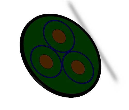
Figure 5 - 3D model of the 3 phase submarine cable

Cabling scenario of the subsea cable used in simulation

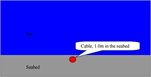
Figure 6 - Cabling scenario of the subsea cable used in simulation

Geometrical model of the submarine cable for simulation

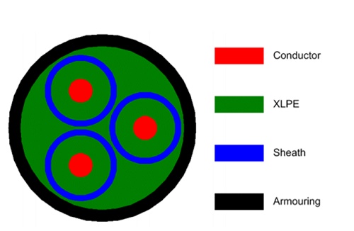
Figure 7 - Geometrical model of the submarine cable for simulation

  The cable is operating at 50 Hz with 135kV AC voltage between phases. As mentioned above AC Electric solver generates the current distributions, E-field distributions and potential differences. In addition, any quantity that can be derived from the basic electromagnetic quantities can be analysed. Figure 8 shows the distribution of the electric field inside all cores of cable. Metallic sheaths in the cable create earthed shields for all cores, so the E-fields are seen to be strictly confined in each core and have a radially symmetric distribution within the dielectric XLPE. Consequently, no E-field is leaked from each core, giving rise to no E-field outside the submarine cable. The electric field E attains its maximum value in the surface of the conductor and it is about 1.0969 e+7 V/m (about 1.0926e+7 V/m in [1]).   E field distribution

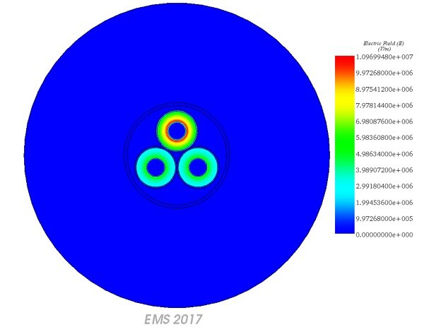
Figure 8 - E field distribution

Conclusion

It is clear from literature that AC submarine cables when improperly designed can cause a great deal of distress to marine ecosystem. Right from the design and sizing of the cable to ensure that there is no electric breakdown to the measurement of field around the cable, EMS for SolidWorks can help engineers design the eco-friendliest submarine AC cables without any compromise. In addition, engineers can optimize the thickness of the insulators around their conductors and save cost on their final cable designs. To try out EMS for SolidWorks, visit www.emworks.com.

Reference

[1]: “Electromagnetic Simulations of 135 kV Three-Phase Submarine Power Cables” by Dr Yi Huang, Department of Electrical Engineering & Electronics Liverpool, L69 3GJ UK retrieved from the following URL - https://corporate.vattenfall.se/globalassets/sverige/om-vattenfall/om-oss/var-verksamhet/vindkraft/kriegers-flak/14-mkb-bilaga-414-cmacs-electrom.pdf