

What is a DC actuator?
Magnetic actuators convert electrical energy into mechanical motion using electromagnetic fields. They come in two types: linear and rotary, depending on the motion direction. DC actuators typically include permanent magnets, solenoids, and ferromagnetic parts. Solenoid actuators (see Figure 1) have a steel armature for linear movement. A DC current through a coil generates a static magnetic flux, creating a magnetic force on the plunger. Both the plunger and coil housing are made of high-permeability ferromagnetic materials to facilitate magnetic field conduction.
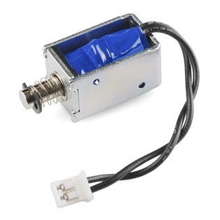
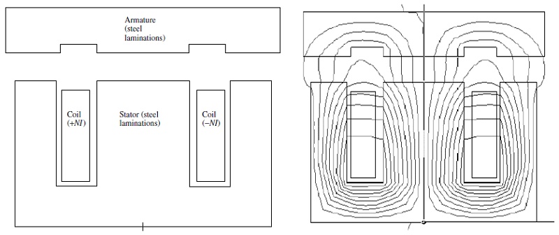 Figure 2 - Typical clapper-type solenoid actuator: (a) geometry, where steel is made up of thin laminations lying in the plane of the page and stacked in the direction out of the page; (b) computer display of flux lines obtained by finite-element analysis [1]
Simulation of a DC actuator using EMWorks
EM simulation plays a crucial role in designing and analyzing DC linear actuators. It helps compute the force generated by the work coil, characterize implemented springs, select suitable materials, and optimize geometric parameters. EMWorks offers both 2D and 3D FEM solutions, with the 2D option ideal for rapid iterative designs due to its quick simulation runs. Meanwhile, the 3D solution validates final model parameters before prototyping and field testing, ensuring design accuracy and performance validation.
Simulation using EMWorks2D
Benchmark 1: Simulation of Clapper Armature Solenoid of Planar Geometry [1]
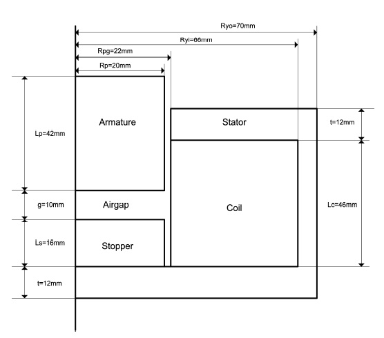
In this example, the 2D model is built from basic sketches. The simulated model has a translational invariance along the z axis. The model geometry is shown in Figure 3. The dimensions are w = 10 mm, Al1 = 5 mm, Al2 = 30 mm, Al3 = 5 mm, Sl1 = 15 mm, Sl2 = 30 mm, Sl3 = 15 mm, and g = 2 mm. The coil is made of copper with 200 turns.
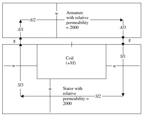
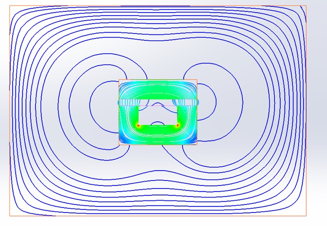
Figure 4 below shows the 2D model meshed in triangles elements. A small mesh size is applied on the air gap. The magnetic flux density is shown in Figure 5 and field lines are shown in Figure 6.
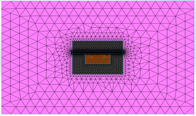
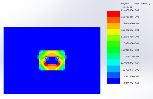
Figure 5 - Magnetic flux density distribution in the model
The force is computed on the moving armature for different currents and air gap lengths. Figure 7 shows the force results computed by EMWorks2D which are in good agreement with reference [1] results.
![EMWorks2D and reference [1] results of the magnetic force](/blog/storage/uploads/2018/07/EMWorks2D-and-reference-1-results-of-the-magnetic-force.jpg)
Benchmark 2: 2D Plunger Solenoid Actuator [1]
A picture of the meshed model is shown in Figure 9. To adjust the mesh in the air gap, a mesh control with a small element size is applied to the air gap.
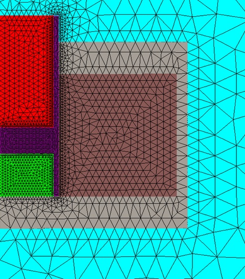
Table 1 shows the computed force for a 2 mm air gap given EMWorks2D and reference [1].
| EMWorks2D | Ref [1] | |
| Force (N) | 19.345 | 19.34 |
Benchmark 3: Force on 3D Clapper Armature Solenoid of Axisymmetric Geometry [1]
This example features a revolving symmetry with a moving armature, as depicted in Figure 10. Key dimensions include g = 2 mm, wa = 8 mm, R1 = 15 mm, R2 = 25 mm, R3 = 30 mm, Z1 = 8 mm, and Z2 = 23 mm. The coil, comprising copper, consists of 2000 turns and is excited by a DC current of 1A (NI=2000 A.t).
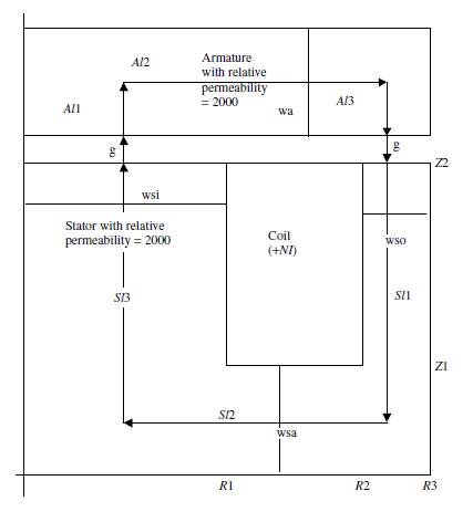
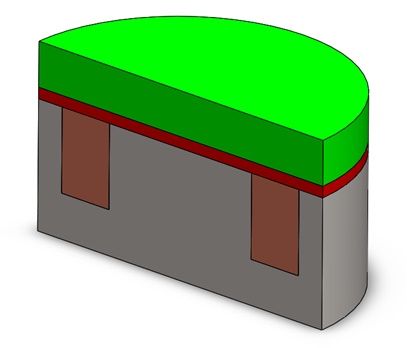
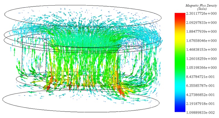
A section view of the 3D model is shown in Figure 11. The magnetic flux density generated by the DC currents in the actuator is plotted in Figure 12 as vectors.
| Relative permeability | 2000 | 10000 |
| EMS results (N) | 283.68 | 290.00 |
Given the axisymmetric nature of the previous model, EMWorks2D proves beneficial for quicker preliminary tests. By utilizing its 2D simplification feature, a 3D CAD model seamlessly converts into 2D surfaces suitable for simulation.
In Figure 13, the depicted direction of magnetic flux density indicates that magnetic forces will draw the moving armature toward the stator. This attraction results in an attractive force magnitude of 279.68 N at a 2 mm air gap and with a relative permeability of 2000.
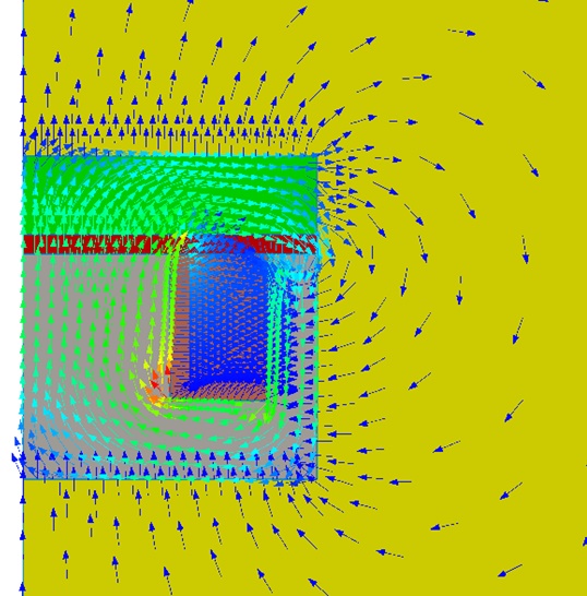
Table 3 shows the computed force on the moving armature using EMWorks2D and reference [1] results. A small error is observed between 2D and 3D results (Table 2) which is due the 2D approximation.
| Relative permeability | EMWorks2D results (N) | Reference [1] results (N) |
| 2000 | 279.68 | 279.41 |
| 10000 | 285.42 | 285.1 |
Electromagnetic simulation is pivotal in refining the design and performance of DC actuators. By accurately modeling electromagnetic fields, these simulations enable engineers to optimize various parameters, such as coil configuration, material selection, and force generation. This comprehensive approach ensures that DC actuators meet stringent performance requirements across different applications. With electromagnetic simulation tools like EMWorks, designers can confidently iterate and refine their designs, ultimately delivering reliable and efficient DC actuators tailored to specific industrial needs.
Reference
[1]: J. R. Brauer, Magnetic Actuators and Sensors: John Wiley & Sons, 2006.