

EMC Simulation of Intel Dual Die CPU
Electromagnetic compatibility (EMC) and electromagnetic interference (EMI) have become crucial concerns for electronic and chip designers due to rising chip density, frequencies, and low supply voltage. Chips now act like antennas, emitting significant electromagnetic energy, especially when accompanied by a heatsink. This article focuses on studying the EMC aspects of an Intel Dual Die CPU around ISM radio bands (2.05 GHz and 4.9 GHz) using HFWorks. It presents electrical results like return loss (S11) and electromagnetic field comparisons with actual measurements. Additionally, thermal results, including temperature distribution with and without the heatsink, are examined.
![Transverse section of Intel Dual Die processor [1]](/blog/storage/uploads/2018/02/Transverse-section-of-Intel-Dual-Die-processor.png)
Simulation of the Dual Die CPU
Figure 1 displays a transverse section of the Intel dual die processor under examination, showcasing its packaging structure, interconnects, and PCB infrastructure, along with a heatsink. For the study, we simplify the internal chip interconnections and focus solely on a stripped-down version, resembling a microstrip patch antenna with two coaxial feeds, as depicted in Figure 2. This simplified model accurately represents the real chip structure for our analysis.
![Applied microstrip patch antenna structure for a dual -die CPU model, (a) layout[1], (b) the Solidworks 3D model of the patch antenna](/blog/storage/uploads/2018/02/Applied-microstrip-patch-antenna-structure-for-a-CPU-model.png)
The pins and interconnections within the integrated circuit are depicted as two coaxial feeds, as shown in Figures 1 and 2. Precise positioning of these feeds greatly impacts the model's performance. Tables 1 and 2 outline the dimensions and material properties used in the simulation. Figure 3 displays the model of the structure and its surrounding air region..
| Name | Typical (mm) |
|---|---|
| Height of Heatsink HH | Variable |
| Height of IHS | 1.65 |
| Height of Die | 1.15 |
| Height of substrate | 1.25 |
| Depth of TIM | 0.1 |
| Depth of Die attach material | 0.1 |
| Depth of IHS Sealant | 0.1 |
| Length of Heatsink | 67.5 |
| Width of Heatsink | 67.5 |
| Length of Die | 11.9 |
| Width of Die | 9.0 |
| Length of substrate | 37.5 |
| Width of substrate | 37.5 |
| Length of IHS External | 34 |
| Width of IHS External | 34 |
| Length of IHS Internal | 26 |
| Width of IHS Internal | 26 |
| Name | Materials | Permittivity | Conductivity(Siemens/m) |
|---|---|---|---|
| Substrate | FR4 epoxy | 4.4 | 0 |
| Die | Silicon dioxide | 4 | 0 |
| IHS | Aluminum | 1 | 3.8x10⁷ |
| Heatsink | Aluminum | 1 | 3.8x10⁷ |
| TIM | Silicone | 1.8 | 0 |
| Die attach material | Silver | 1 | 6.1x10⁷ |
| IHS Sealant | Epoxy | 1.8 | 0 |
The CPU's antenna model is excited through two circular wave ports with a specified impedance. These ports are positioned at the bottom of the substrate and linked to two copper coaxial feeds, which make contact with the IHS [1].
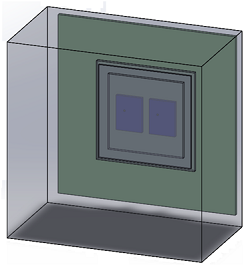 Figure 3 - 3D model of Intel Dual Die CPU processor with Heatsink
Simulation and results
A. Effects of the Heatsink
Simulation results with and without the heatsink on the CPU reveal distinct resonant frequencies. Without the heatsink, resonance occurs at 2.05 GHz with a reflection coefficient of -11.45 dB and 4.9 GHz with a coefficient of -20.54 dB at port 1, and 2.05 GHz with a coefficient of -4.32 dB, and 4.9 GHz with a coefficient of -18.83 dB at port 2. With the heatsink, resonance shifts to 2.3 GHz with a coefficient of -25.83 dB and 5.45 GHz with a coefficient of -12.90 dB at port 1, and 2.3 GHz with a coefficient of -3.41 dB and 5.45 GHz with a coefficient of -13.45 dB at port 2. HFWorks results closely align with measured data, as depicted in Figure 4, while far-field results at 2.05 GHz, shown in Figure 5, also demonstrate a strong correlation with measured data.
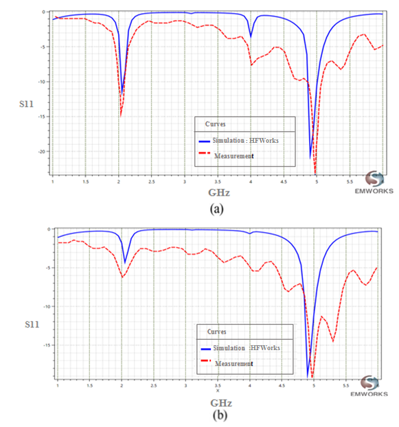
Figure 4 - (a) Reflection coefficient at port1. (b) Reflection coefficient at port 2.
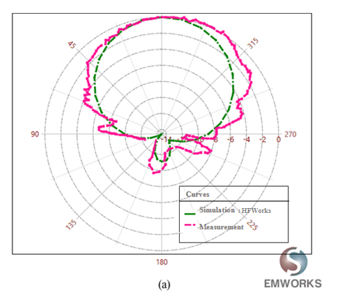
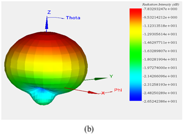
Figure 5 - (a) 2D plot of radiation pattern at 2.05 GHz, (b) 3D plot of radiation pattern at 2.05 GHz
B. Height of Heatsink
Figure 3 illustrates the heatsink, represented as a solid block devoid of fins. Various simulations were conducted to analyze how the heatsink's height impacts both field and circuit results, aiming to optimize the structure of the Dual-die CPU with the heatsink. Table 1 indicates that the heatsink's height minimally affects the reflection coefficient at both port 1 and port 2. Consequently, the resonant frequency and scattering parameters of the Intel dual die CPU are predominantly influenced by its internal structure rather than its mounted components.
| Simulation Setup HFW (Port1) | Reflection coefficient | |
| GHz | dB | |
| Height of Heatsink HH=37mm | 1.75 | -16.69169 |
| 5.525 | -6.11 | |
| Height of Heatsink HH=42mm | 1.75 | -16.74 |
| 5.525 | -6.09 | |
| Height of Heatsink HH=47mm | 1.75 | -25.28 |
| 5.525 | -11.21 | |
| Simulation Setup HFW (port2) | Reflection coefficient | |
| GHz | dB | |
| Height of Heatsink HH=37mm | 1.75 | -8.91 |
| 5.525 | -20.2224 | |
| Height of Heatsink HH=42mm | 1.75 | -11.38 |
| 5.525 | -13.10 | |
| Height of Heatsink HH=47mm | 1.75 | -11.42 |
| 5.525 | -12.25 | |
C. Heat Simulation
Figure 6 illustrates the temperature distribution within the CPU resulting from the conductor and dielectric losses of the modeled structure.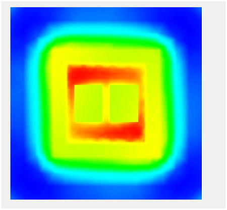
Conclusion
The EMC simulation of Intel's Dual Die CPU, crucial for addressing electromagnetic compatibility concerns in chip design, proves insightful. By leveraging HFWorks, resonant frequencies, reflection coefficients, and thermal distributions were analyzed, providing valuable insights for optimizing CPU performance. The study highlights the minimal impact of heatsink height on CPU behavior, affirming the dominance of internal structural factors. This comprehensive approach, validated against measured data, contributes to enhancing the reliability and efficiency of modern chip designs.