

Introduction
This blog post delves into the nuanced design of WR2300 half-height rectangular waveguides, essential for power coupling in accelerator cavities. It zeroes in on the transition section, crucial for tailoring iris coupling based on varying cavity requirements. Highlighted parameters include return loss, insertion loss, resonant frequency, and thermal behavior. We also showcase how HFWorks facilitates the design and simulation of RF couplers, offering a glimpse into coupled RF and thermal analysis through its S-Parameters module.
Design and Simulation
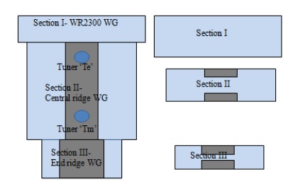
Figure 1 displays the CAD design of the coupler structure, which is comprised of three distinct parts: an incoming rectangular WR2300 half-height waveguide designated as Part I, a central ridge waveguide termed Part II, and an end ridge identified as Part III, as depicted in Figure 2. The dimensions of the straight ridge waveguide coupler are 400mm x 400mm x 150mm.
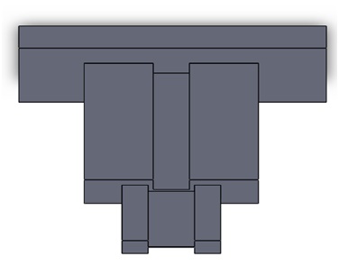
Figure 2 presents a schematic side view of the waveguide coupler, illustrating its design and structure. The relationship between the cutoff frequency and the ridge gap for the TE10 mode, simulated using ATLASS[1], is depicted in Figure 3.
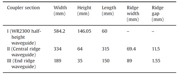
These parameters are summarized in Table 1.
Results
Figure3, shows the variation of the cut-off frequency for TE10 mode using ATLASS, by varying the ridge gap.
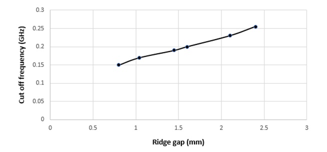
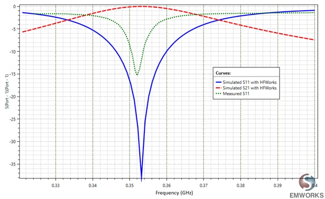
Figure 4 illustrates both the simulated and measured results of the coupler's return loss (S11) and insertion loss (S21) using HFWorks. Additionally, it is shown that the waveguide coupler resonates at 0.353 GHz, as indicated in Figure 4.
HFWorks automatically calculates the conductor loss, or the thermal load, on the coupler walls, considering an incident power of 250 kW. This computed thermal load is then integrated into the thermal module. The surrounding air is modeled with a convective heat transfer coefficient (h) of 1000 W/m²K and an ambient temperature of 293 K.
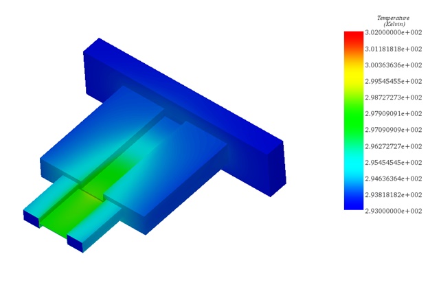
Figure 5 displays the temperature distribution, demonstrating a minimal increase in temperature despite the high incident power of 250 kW. This indicates the waveguide's robustness against thermo-structural defects under such power conditions.
Conclusion
In this exploration of RF waveguide coupler design, we've uncovered the pivotal role it plays in determining the performance of high-power accelerator systems. By focusing on key parameters such as return loss, insertion loss, resonant frequency, and thermal behavior, this application note not only answers critical questions on the impact of design on performance but also demonstrates how simulation tools like HFWorks can be instrumental in optimizing these systems. As researchers and engineers delve into the nuances of waveguide design, such insights become invaluable for advancing accelerator technology.
References
[1] https://www.emworks.com/product/ATLASS [2] Rajesh Kumar, Mentes Jose, G.N. Singh, Girish Kumar and P.V. Bhagwat "RF characterization and testing of ridge waveguide transitions for RF power couplers ", published at Nuclear Instruments and Methods in Physics Research A 838, pp. 66-7, 2016