

PIFA Antenna - Design and Simulation
The mobile phone industry demands the development of compact and efficient antennas for communication. Planar Inverted Antenna F (PIFA) stands out in this domain due to its compact size and the direction of its radiated field, which minimizes exposure to the user’s head, making it preferable over alternatives like whip, rod, or helix antennas.
This article outlines how HFWorks aids electrical engineers in designing, simulating, and optimizing dual-band PIFA antennas for GPS and WiMAX applications. It highlights a PIFA antenna designed in SolidWorks, featuring a driven element with a C-shaped patch and a shorting strip, alongside a parasitic element with an inverted L shape. These elements are positioned over a finite ground plane with air as the substrate, demonstrating the antenna's structural efficiency.
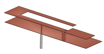
Figure 1 - 3D model of a PIFA antenna
The schematic of the dual-band antenna, illustrated in figure 2, features a coaxial feed line with a 50 Ohm impedance. Electrical parameters for such a structure can be analyzed using ATLASS[1], enabling precise calculations of its performance.
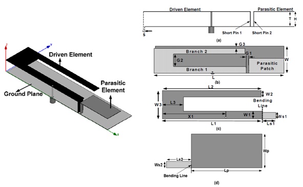
Figure 2 - Schematic diagram of the PIFA antenna
To simplify the design process, geometrical parameters are compiled in a file and imported as equations, detailed in Table 1 for efficient implementation.
Table 1- Geometric parameters of the PIFA antenna
| Variable | Value (mm) | Variable | Value (mm) |
| L | 100 | W3 | 22 |
| W | 24 | Ls1 | 9.5 |
| H | 9.7 | Ws1 | 5 |
| T | 9.3 | Ls2 | 9.5 |
| S | 1 | Ws2 | 2.5 |
| G1 | 2 | Lp | 27 |
| G2 | 11 | Wp | 13 |
| G3 | 2 | Lg | 99 |
| L1 | 71 | Wg | 24 |
| L2 | 70 | X1 | 45 |
| L3 | 15 | X2 | 44 |
| W1 | 6 | Y | 1 |
| W2 | 5 |
Simulation Results
Figure 3 presents the simulated S-Parameters of the PIFA antenna via HFWorks, showing operation at two frequencies: 1.595 GHz with a reflection coefficient of -26.90 dB, and 3.363 GHz with a reflection coefficient of -45.96 dB. The lower mode achieves an impedance bandwidth of 90 MHz, whereas the higher mode offers a broader bandwidth of 135 MHz, adequately meeting the bandwidth needs for GPS and WiMAX applications.
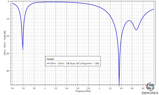
Figure 3 - Return loss of the PIFA antenna (dB)
The far-field simulation reveals the field distribution surrounding the model at a distance from the structure. Figure 4 displays the 3D gain pattern at the first resonance frequency of 3.363 GHz, while Figure 5 provides a 2D visualization of the same gain pattern.
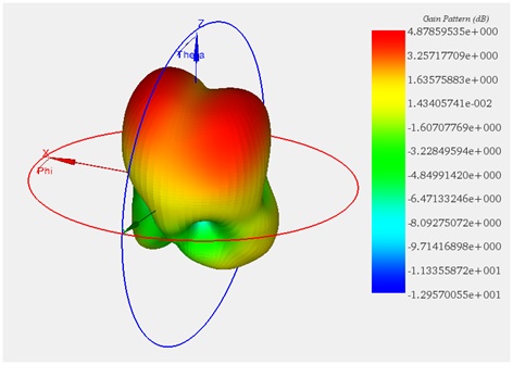
Figure 4 - 3D plot of the gain pattern at 3.363 GHz
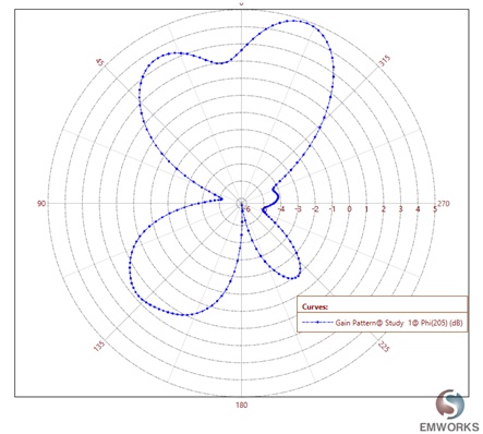
Figure 5 - 2D plot of the gain pattern at 3.363 GHz
Parameterization
To explore the impact of adjusting the metal strip's area between branch 1 and branch 2, as shown in Figure 2, it's necessary to alter the length L3 and examine its effect on the S parameters. HFWorks enables designers to test various scenarios, ensuring optimal performance by understanding how specific adjustments influence the final outcome. This tool is also integrated with the design software, allowing for direct simulation of the model without needing to re-import data after each design change. Figure 6 indicates that while the impedance bandwidth in the GPS band remains largely stable with a reduction in L3, it does adversely affect impedance matching performance. Reducing L3 increases the overlap between the branches and the ground plane of the driven element.
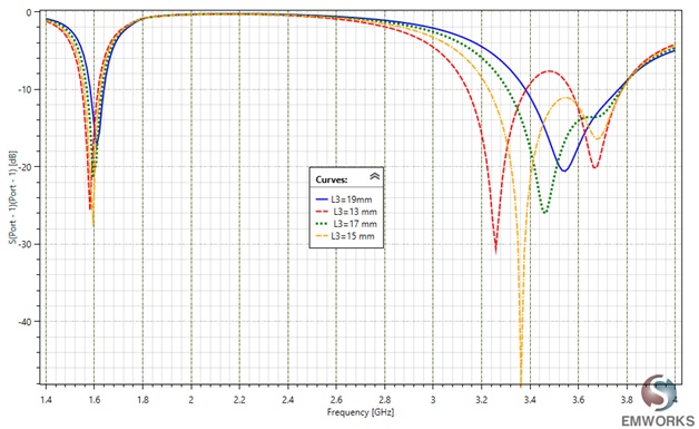
Figure 6 - Return loss as a function of dimension, L3 of a PIFA antenna
Adjusting the area by changing the length L3 increases the capacitive reactance, leading to a decrease in the resonant frequencies within the WiMAX band. Interestingly, as L3 decreases to certain values, the bandwidth of the WiMAX band expands while maintaining the higher frequency constant. Moreover, when L3 is reduced to less than 15 mm, the wide band spectrum disappears, giving way to dual band behavior. This phenomenon highlights the critical role of specific geometric modifications in tuning the antenna's performance for targeted frequency bands.
This blog provides a deep dive into optimizing dual-band Planar Inverted F Antennas (PIFAs) for the mobile industry, specifically for GPS and WiMAX applications. It highlights the importance of precise design and simulation using HFWorks to enhance antenna efficiency and functionality. Through detailed parameterization and simulation results, the note demonstrates how adjustments in geometrical parameters, like the length of the metal strip, significantly influence the antenna's performance, offering insights into achieving optimal design configurations. This guidance is invaluable for engineers aiming to develop compact, high-performance antennas for today's mobile communication demands.
References
[1] https://www.emworks.com/product/ATLASS [2] Mayank Agarwal, Rajesh Singh, and Manoj Kumar Meshram " Dual-Band Linearly Polarized Planar Inverted-F Antenna (PIFA) for GPS/WiMAX Applications", presented at Students Conference on Engineering and Systems (SCES), 2013 IEEE.