Switched Reluctance Motor (SRM)
Switched Reluctance Motors (SRMs) are known for their unique design featuring phase coils on opposite stator poles and a rotor composed solely of laminated steel without windings or magnets. This simplicity and robustness make SRMs ideal for high-speed applications, boasting high power density critical for electric vehicle (EV) traction motors. Their promising attributes position SRMs as a top choice for EV applications.
Model of a Switched Reluctance Motor
The designed switched reluctance motor is characterized as a three-phase machine, featuring six inner stator poles, eight outer rotor poles, and a shaft, as depicted in Figure 1.
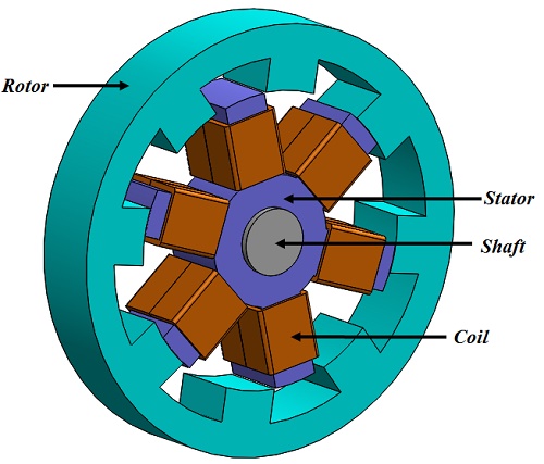
Figure 1 - 3D model of a switched reluctance motor
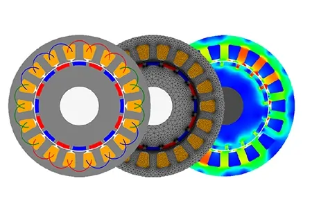
EMS Simulation of the In-Wheel Switched Reluctance Motor
In EMS, switched reluctance motors are evaluated using Transient Magnetic simulations that incorporate motion. EMS measures time-domain magnetic fields, calculating essential metrics such as magnetic flux density (B), magnetic field (H), and current distribution (J). It also derives important performance indicators like forces, torques, energy, losses, flux linkage, inductance, and induced voltage.
For these simulations, parameters are set as follows: Start Time at 0 s, End Time at 0.24 s, and Time Increment at 0.0025 s.
EMS study
In this simulation, the rotor and shaft are dynamic elements encapsulated in an air region to prevent interaction with stationary parts. They move due to electromagnetic forces, with their positions updated based on torque calculations at each time step, creating a feedback loop for precise motion analysis.
An initial torque of 0 N.m is applied to the shaft's frontal face, later adjusted by real-time torque values from the electromagnetic force calculations to simulate motion.
The motor features six stator cores activated by three-phase coils, each modeled with 120 turns and a 9 AWG diameter. Current entry points and coil excitation at 45 A are depicted, showcasing the motor's electromagnetic operation.
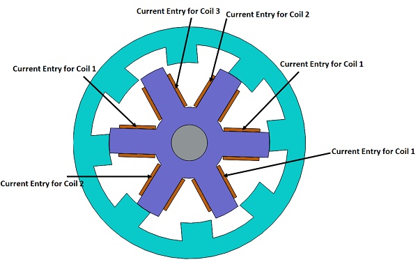
Figure 2 - Current entry ports for the three wound coils
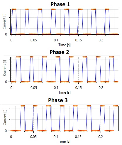
Figure 3 - Current excitation of the three phases
Materials
The simulated model consists of a stator, rotor, shaft, coils, Inner Air, Band, and Outer Air, with material properties detailed in Table 1.
Table 1: Materials used in the EMS simulation
| Component | Material | Relative permeability | Conductivity (S/m) |
| Stator, rotor, shaft | M-19 | Nonlinear | 0 |
| Coils | Copper | 0.99991 | 5.8e+007 |
| Band, Inner Air, Outer Air | Air | 1 | 0 |
Magnetic flux density computation
In designing a switched reluctance motor, selecting the appropriate ferromagnetic core material heavily depends on the magnetic flux density. EMS calculates this density at each time step, corresponding to the rotor's position. According to comparisons with reference [1], the peak magnetic flux density reached 2.11 Tesla, as detailed in Table 2.
| Parameter |
EMS result | Reference [1] result |
| Magnetic flux density maximum value | 2.11 Tesla |
1.9 Tesla |
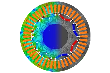
3D fields generated by the Switched Reluctance Motor
EMS generates 3D plots illustrating the magnetic flux density, with Figure 4 displaying the 3D vector plot and Figure 5 presenting the 3D plot of the magnetic flux density.
Figure 4 - 3D Vector plot of magnetic flux density
Figure 5 - 3D plot of the magnetic flux density
Conclusion
Switched Reluctance Motors (SRMs) are highly regarded for their straightforward design, featuring phase coils on opposite stator poles and a rotor made solely of laminated steel. Their simplicity and durability make them well-suited for high-speed applications, particularly traction motors in electric vehicles (EVs), where high power density is crucial. With promising attributes, SRMs emerge as a top contender for EV propulsion systems. EMS simulations, integrating motion, provide crucial insights into SRM performance metrics such as magnetic flux density, forces, torques, and losses. Comparisons with reference data confirm the accuracy of these simulations, demonstrating peak magnetic flux density values of 2.11 Tesla. 3D visualizations further aid in understanding the magnetic field distribution within the motor. These findings underscore the potential of SRMs in advancing EV technology, offering efficiency and reliability in a compact and robust package.
References
[1] K. Cakir A. Sabanovic, “In-wheel Motor Design for Electric Vehicles” 9th IEEE International Workshop on Advanced Motion Control, 2006.