What is a DC actuator?
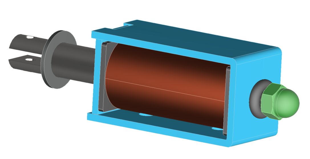
Magnetic actuators, converting electrical to mechanical energy via electromagnetic fields, are divided into linear or rotary types. DC actuators, incorporating permanent magnets, solenoids, and ferromagnetic materials, use solenoids for linear actions. These solenoids, illustrated in Figure 1, operate by sending DC current through a coil to produce a static magnetic flux, thereby generating force on a high permeability ferromagnetic plunger for efficient field conduction.
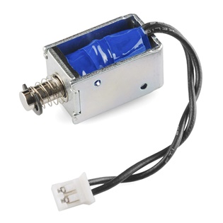
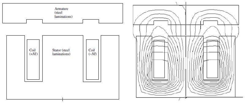 Figure 2 - Typical clapper-type solenoid actuator: (a) geometry, where steel is made up of thin laminations lying in the plane of the page and stacked in the direction out of the page; (b) computer display of flux lines obtained by finite-element analysis [1]
Simulation of a DC Actuator
EM simulation plays a pivotal role in designing and evaluating DC linear actuators, enabling precise calculations of coil-generated forces, spring characteristics, material selection, and actuator geometry optimization. EMWorks supports this with both 2D and 3D FEM solutions; 2D for rapid initial designs due to its quick simulation capabilities, and 3D for validating final design parameters, ensuring accuracy before prototyping and testing commence.
Simulation using EMWorks2D
Benchmark 1: Simulation of Clapper Armature Solenoid of Planar Geometry [1]
In this example, the 2D model, created from basic sketches, demonstrates translational invariance along the z-axis, as illustrated in Figure 3. The model's dimensions include a width (w) of 10 mm, with aluminum sections Al1, Al2, and Al3 measuring 5 mm, 30 mm, and 5 mm, respectively, and steel sections Sl1, Sl2, and Sl3 at 15 mm, 30 mm, and 15 mm. A gap (g) of 2 mm separates the components. The coil, crafted from copper, comprises 200 turns, indicating a detailed design for precise EM simulation analysis.
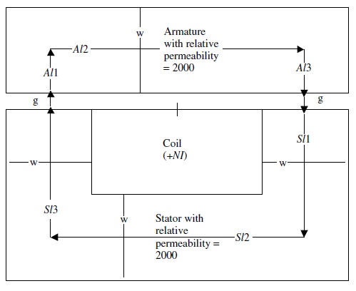
Figure 4 displays the 2D model meshed with triangular elements, applying a fine mesh size specifically to the air gap for increased accuracy in simulation. The magnetic flux density and the field lines are respectively illustrated in Figures 5 and 6, providing a detailed visualization of the electromagnetic interactions within the model.
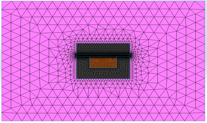
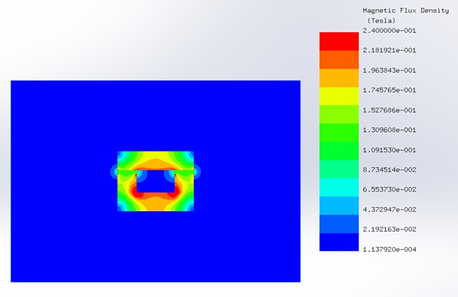
Figure 5 - Magnetic flux density distribution in the model
The force exerted on the moving armature is calculated across varying currents and air gap lengths. Figure 7 presents the force outcomes determined by EMWorks2D, demonstrating a strong correlation with the results from reference [1], indicating the simulation's accuracy and reliability in modeling electromagnetic behaviors.
![EMWorks2D and reference [1] results of the magnetic force](/ckfinder/userfiles/images/EMWorks2D-and-reference-%5B1%5D-results-of-the-magnetic-force.jpg)
Benchmark 2: 2D Plunger Solenoid Actuator [1]
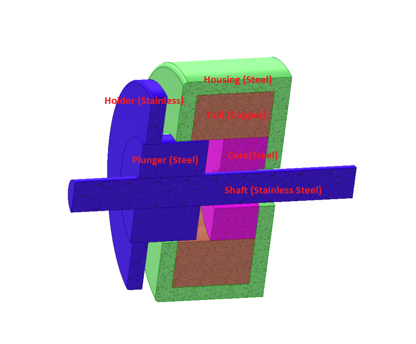
This example focuses on a 3D model of a plunger solenoid actuator, where the plunger exhibits cylindrical geometry and the solenoid is axisymmetric. Magnetic force is applied solely at the end of the plunger. Figure 8 illustrates the geometric parameters of the setup, with 400 turns and an injected current of 4A. The coil comprises copper, while the remaining components are crafted from ferromagnetic material boasting a relative permeability of 2000.
A visual representation of the meshed model is depicted in Figure 9. To fine-tune the mesh within the air gap, a mesh control feature is utilized, applying a smaller element size specifically to the air gap region.
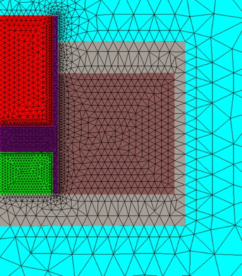
Table 1 presents the calculated forces for a 2 mm air gap as determined by EMWorks2D and reference [1].
| EMWorks2D | Ref [1] | |
| Force (N) | 19.345 | 19.34 |
Benchmark 3: Force on 3D Clapper Armature Solenoid of Axisymmetric Geometry [1]
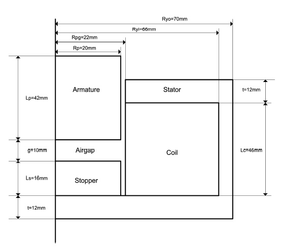
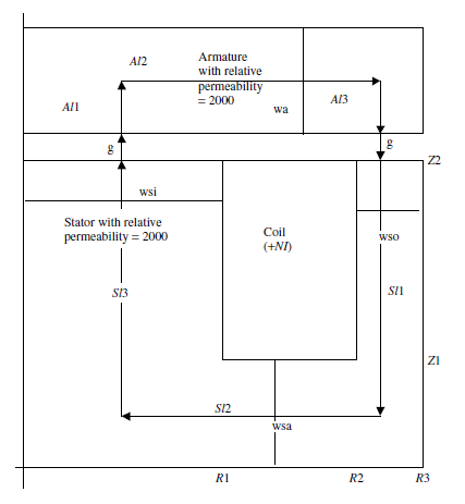
The provided example demonstrates a rotational symmetry with a moving armature. Illustrated in Figure 10 is the geometry of the axisymmetric actuator, featuring key dimensions such as g = 2 mm, wa = 8 mm, R1 = 15 mm, R2 = 25 mm, R3 = 30 mm, Z1 = 8 mm, and Z2 = 23 mm. The coil, comprising 2000 turns, is constructed from copper and subjected to a DC current excitation of 1A (NI=2000 A.t).
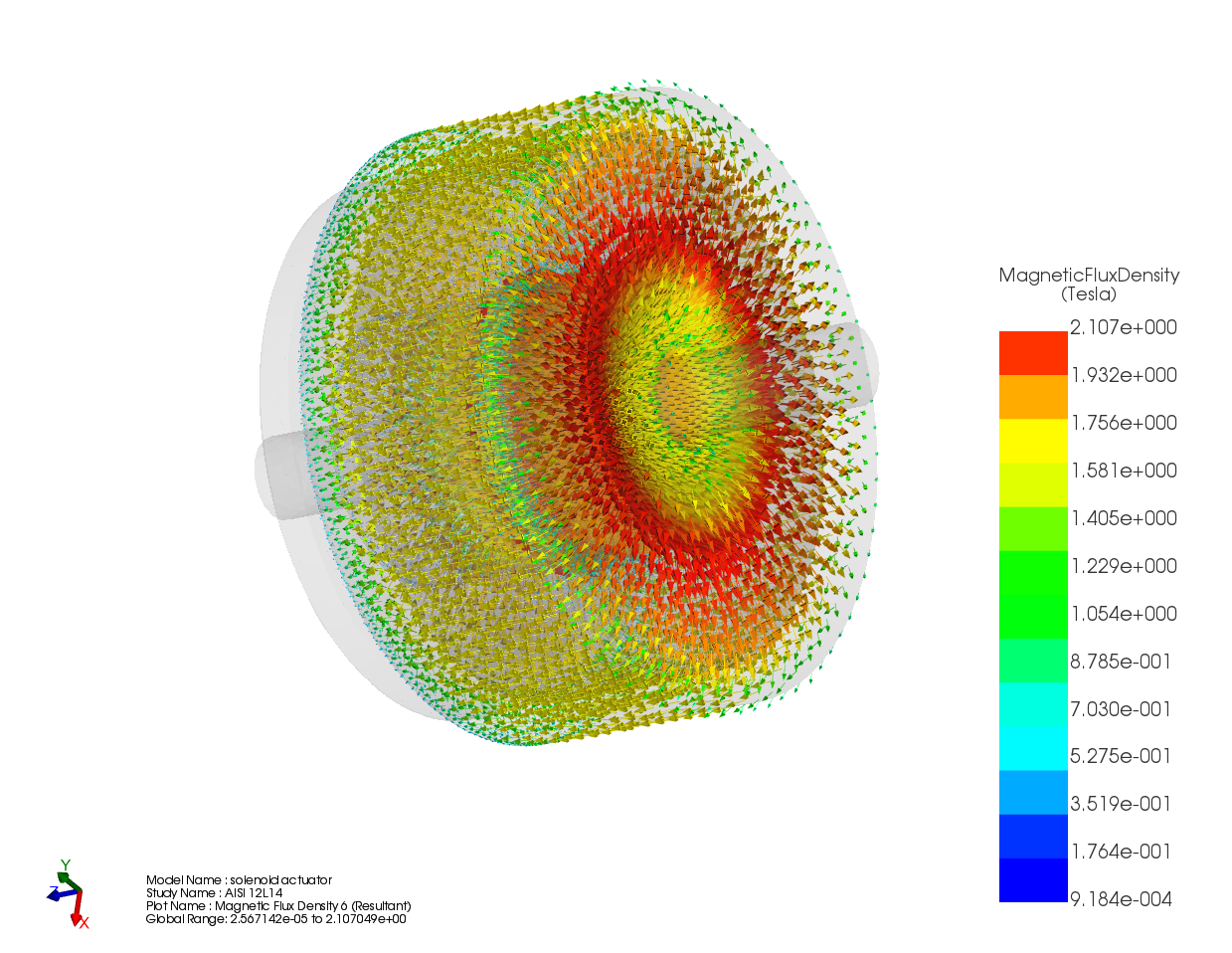
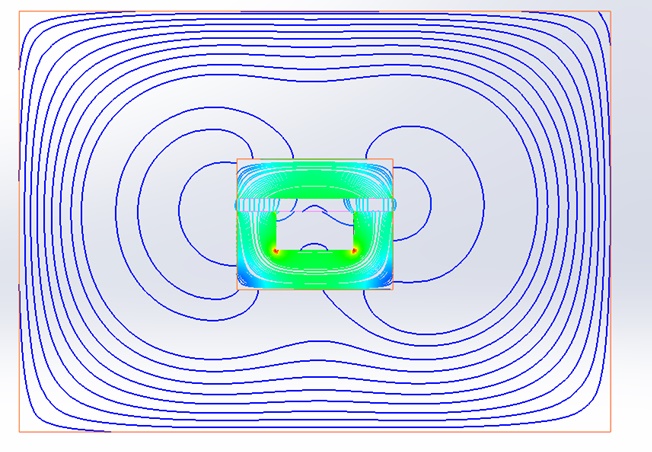
A sectional view of the 3D model is depicted in Figure 11, providing insight into its internal structure. Additionally, Figure 12 showcases the magnetic flux density distribution resulting from the DC currents within the actuator, represented by vectors.
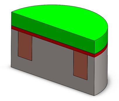
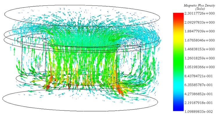
Table 2 presents the calculated force exerted on the moving armature using EMS for two distinct relative permeability values.
| Relative permeability | 2000 | 10000 |
| EMS results (N) | 283.68 | 290.00 |
Utilizing the axisymmetric geometry of the previous model, EMWorks2D proves effective in reducing computation time for preliminary tests. By employing the 2D simplification feature, a 3D CAD model seamlessly converts into 2D surfaces suitable for simulation.
Figure 13 depicts the direction of magnetic flux density within the 2D model, indicating that magnetic forces will attract the moving armature toward the stator. At a 2 mm air gap and with a relative permeability of 2000, the attractive force magnitude measures 279.68 N.
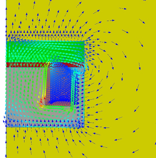
Table 3 illustrates the computed force on the moving armature obtained from EMWorks2D and compared with the results from reference [1]. A minor discrepancy is evident between the 2D and 3D results (as shown in Table 2), attributed to the 2D approximation.
| Relative permeability | EMWorks2D results (N) | Reference [1] results (N) |
| 2000 | 279.68 | 279.41 |
| 10000 | 285.42 | 285.1 |
Conclusion
The application note delves into the simulation of DC linear actuators using electromagnetic (EM) fields, employing both 2D and 3D Finite Element Method (FEM) solutions provided by EMWorks. These simulations enable precise calculations of force exertion by various actuator designs under different conditions, validating the tool's accuracy and reliability. While 2D models offer quicker simulation times for preliminary tests, 3D models ensure accuracy before prototyping. Results from both simulations align closely with reference data, demonstrating EMWorks' effectiveness in analyzing different actuator geometries and operating conditions. Examples cover various actuator types, including clapper-type solenoids and plunger solenoids, showcasing the tool's versatility. By leveraging the axisymmetric nature of certain designs, EMWorks2D efficiently reduces computation time while maintaining accuracy. Overall, the simulations provide valuable insights for optimizing performance and efficiency in real-world applications, contributing to advancements in DC linear actuator design and evaluation.
References
[1]: J. R. Brauer, Magnetic Actuators and Sensors: John Wiley & Sons, 2006.