An Actuator with Ferrofluid
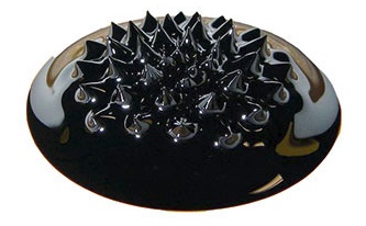
Innovations in linear solenoid actuators now incorporate ferrofluids to boost efficiency and reduce energy use. These magnetic fluids enhance magnetic responsiveness and lower power requirements, leading to improved performance in industrial applications like valve systems and fuel injection. This leap in actuator design marks a significant advancement in electromagnetic technologies, optimizing force and reliability with minimal energy consumption.
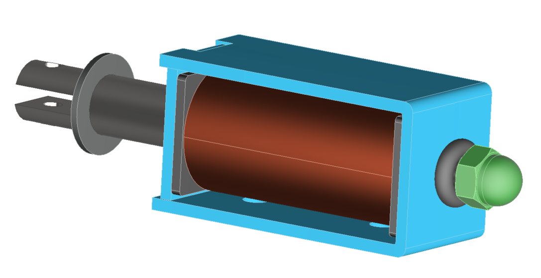
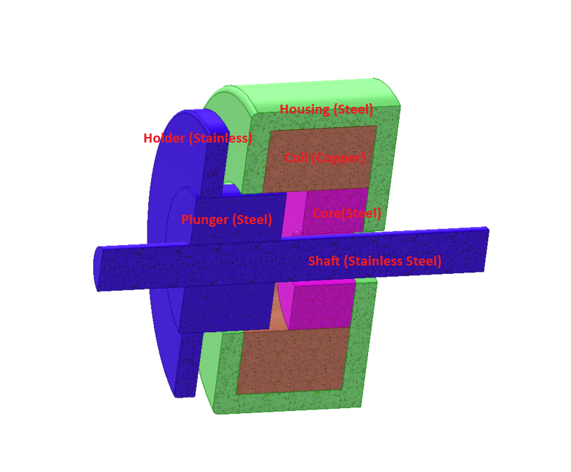
CAD Model
The electromagnetic actuator under investigation features a stationary ferromagnetic core, a copper DC coil with 500 turns of 1mm diameter wire, a movable ferromagnetic plunger, and a ferrofluid-filled gap. Both the core and plunger are made of Carbon Steel 12040, characterized by its B-H properties. Its operation hinges on activating the ferromagnetic circuit with a DC current through the coil, generating a magnetic field (B) that exerts a magnetic force (Fm) on the plunger. Movement occurs when this force overcomes the combined resistances, including friction and hydrodynamic resistance, alongside any external forces.
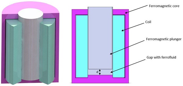
Table 1 - Component` Dimensions
| Part | Dimensions (mm) | ||
| Core | Diameter: 48 | Height: 63 | Thickness: 3 |
| Coil | Diameter: 41 | Height: 53 | Thickness: 10 |
| Plunger | Diameter: 20 | Height: 53 | |
Material properties
Table 2 - Material properties
| Density (Kg/ $$ \textstyle m^3 $$) | Magnetic permeability | Electrical conductivity (S/m) | |
| Copper (Cu) | 8900 | 0.99 | 6 E+07 |
During this investigation, we analyze the static operational characteristics of the actuator under two conditions: one with ferrofluid present (µ > 1) and the other without (µ = 1) in the working gap. We'll discuss two models:
1. The first model employs Linear Carbon Steel 12040 for the core and plunger, with a magnetic permeability of µ = 1000.
2. The second model utilizes a nonlinear material characteristic defined by a specific BH curve: [provide BH curve details].
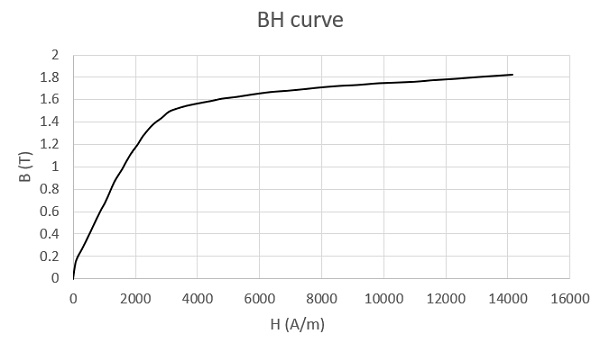
Figure 3 - BH curve of Carbon steel 12040
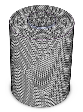
Meshing
Figure 4 displays the meshed model, meticulously crafted with fine mesh control applied throughout to ensure accuracy in the simulation results.
A series of simulations were conducted to analyze the influence of Ferrofluid on the actuator's behavior across different plunger positions. These simulations covered a range of Ferrofluid permeability values from 1 to 50. The results obtained from these analyses are presented below.
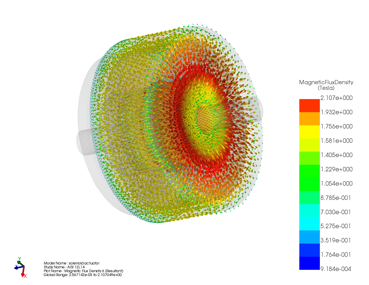
Magnetic field results
Case 1: Linear ferromagnetic Carbon steel
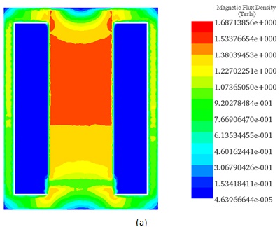
Figures 5, 6, and 7 provide cross-sectional view plots depicting the flux density and magnetic field distribution. These plots illustrate the behavior across different plunger positions and Ferrofluid permeability values in the linear ferromagnetic Carbon Steel material case.
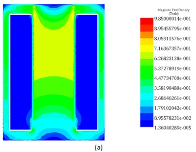
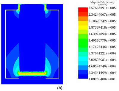
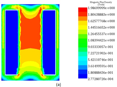
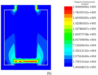
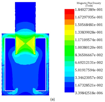
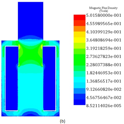
Table 3 - Comparative table of Flux density results between EMS and Ref [3].
| Magnetic flux results | EMS | Reference [3] |
| µ=1, d=2.5 mm | 0.985 | 0.985 |
| µ=5, d=2.5 mm | 1.98 | 1.71 |
| µ=1, d=35 mm | 0.184 | 0.184 |
| µ=5, d=35 mm | 0.5 | 0.499 |
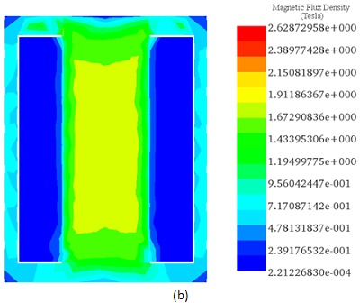
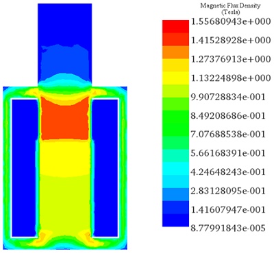
Case 2: Non-Linear ferromagnetic Carbon steel
In simulations involving non-linear ferromagnetic Carbon Steel material, the obtained magnetic flux results are as follows:
Magnetic force results
Case 1: Linear ferromagnetic Carbon steel
In the linear problem scenario, we evaluate the electromagnetic force generated based on the relative magnetic permeability of ferrofluid at various working gaps.
Figure 10 illustrates the variation of force versus plunger position for a ferrofluid permeability of 50. The magnetic force shows an inverse relationship with the plunger position, reaching significant values for smaller ferrofluid gaps.
For a fixed plunger position set to d = 2.5 mm from the core base, the obtained force results are presented in Figure 11. Higher magnetic permeabilities of the ferrofluid correspond to higher generated force values, with the maximum electromagnetic force (Fmax) reaching approximately 73 N with µ = 50. Comparison between EMS and Reference [3] results reveals a strong alignment.
.
![EMS and Reference [3] results for different plunger positions for µ=50](/ckfinder/userfiles/images/EMS-and-Reference-%5B3%5D-results-for-different-plunger-positions-for-%C2%B5%3D50.jpg)
![EMS and Reference [3] results for different ferrofluid permeabilities at plunger position of d=2.5 mm](/ckfinder/userfiles/images/EMS-and-Reference%5B3%5Dresults-for-different-ferrofluid-permeabilities-at-plunger-position-of-d%3D2.5mm.jpg)
Figure 11 - EMS and Reference [3] results for different ferrofluid permeabilities at plunger position of d=2.5 mm.
Case 2: Non-Linear ferromagnetic Carbon steel
In the analysis of non-linear ferromagnetic carbon steel, simulations explored various plunger positions and Ferrofluid permeability values to determine the force generated by Ferrofluid's influence.
Figure 12 illustrates force variations versus plunger position with a Ferrofluid permeability of 5. The magnetic force shows an inverse correlation with the plunger position, particularly significant in smaller gaps.
For a fixed plunger position at d = 2.5 mm from the core base, Figure 13 displays the obtained force results. In smaller gaps, electromagnetic force notably increases within a relative magnetic permeability range of 1 to 5, gradually decreasing with higher permeability. The maximum electromagnetic force (Fmax) reaches around 29 N with µ = 5. EMS and Reference [3] results exhibit strong consistency.
![EMS and Reference [3] results for different plunger positions for µ=5](/ckfinder/userfiles/images/EMS-and-Reference%5B3%5Dresults-for-different-plunger-positions-for-%C2%B5%3D5.jpg)
![EMS and Reference [3] results for different ferrofluid permeabilities at plunger position of d=2.5 mm](/ckfinder/userfiles/images/EMS-and-Reference%5B3%5Dresults-for-different-ferrofluid-permeabilities-at-plunger-position-of-d%3D2.5%20mm.jpg)
Figure 13 - EMS and Reference [3] results for different ferrofluid permeabilities at plunger position of d=2.5 mm.
Conclusion
This application note explores the innovative use of ferrofluids in linear solenoid actuators, showcasing a significant leap in actuator design for improved efficiency and reduced energy consumption. By incorporating ferrofluids, which enhance magnetic responsiveness and lower power requirements, the actuator demonstrates enhanced performance, particularly beneficial for industrial applications like valve systems and fuel injection. The study employs a detailed CAD model of an electromagnetic actuator featuring a stationary ferromagnetic core, a movable plunger, and a ferrofluid-filled gap, highlighting the use of Carbon Steel 12040 for core and plunger materials for their favorable B-H properties.
Simulations assess the actuator's static behavior with and without ferrofluid, exploring two material models: one linear and the other nonlinear, characterized by specific BH curves. Meshed models ensure accuracy in capturing magnetic flux density and field distribution, revealing the significant impact of ferrofluid permeability on magnetic force. Results confirm that ferrofluid presence amplifies magnetic force, especially at smaller gaps, showcasing ferrofluid's potential to enhance actuator performance.
The study concludes that integrating ferrofluids in actuators marks a notable advancement in electromagnetic technology, optimizing force output and reliability while minimizing energy use, establishing a promising direction for future actuator designs.
References
[1] http://112.216.150.106:8080/paros/download/pdf/E1MGAB_2017_v22n1_109.pdf
[2] https://www.computerhope.com/jargon/f/ferrofluid.htm
[3] Terzova, A. I., V. M. Mateev, and I. Y. Marinova. "Modelling of electromagnetic actuator with ferrofluid." CEMBEF 2013(2013): 75-78.