IPMSM
As the need for more efficient and reliable electric motors grows, new ideas have been developed to achieve better performance characteristics such as higher torque density, lower torque ripple rate, and lower power losses. The optimization procedure itself contains various aspects including the analysis of different design parameters to reach the best possible performance [1]. One of the interesting solutions is the “asymmetrical” design that offers promising alternatives to enhance the efficiency of electric motors [2].
The following figure draws a comparison between the symmetric and asymmetric Interior Permanent Magnet Synchronous Motors (IPMSMs)
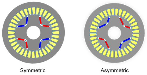
Fig. 1. Comparison Between Symmetric and Asymmetric IPMSMs
Design Optimization Objectives
In asymmetric IPMSM design, reaching improved torque characteristics is the main target. Therefore, the selected objectives are maximum average torque, minimum torque ripple rate, and minimum cogging torque.
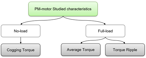
Fig. 2. The Studied Torque-Related Characteristics of the IPMSMs
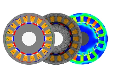
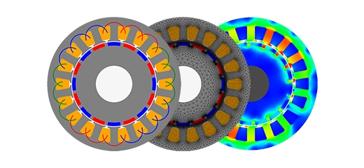
EMWorks2D Solution
To analyze the selected optimization objectives, the transient magnetic analysis coupled with a rotational motion setup is used. Considering the different nature of selected optimization objectives, the studies including No-load analysis, full-load analysis, and cogging torque analysis have been conducted separately.
Design Specifications
The following table shows a summary of the design specifications of both symmetric and asymmetric IPMSM. As can be seen, the stator dimensions alongside the excitation parameters are identical. The only difference between the two motors is the magnet-barrier shape and size.
| Configuration | Value |
| Number of Slots | 36 |
| Based speed | 1500 rpm |
| Winding Configuration | Distributed |
| Current amplitude | 38.7 A |
| Stator OD | 67.41 mm |
| Stack length | 100 mm |
| Core material | 50 JN 800 |
| Permanent magnet | N28H |
| Conductor | Copper |
Table 1. Design Specifications of both IPMSMs
Simulation Results
In this section, the cogging torque, the average torque, and torque ripple results obtained with EMWorks 2D will be compared:
Cogging Torque
The cogging torque is one of the important output parameters of the PM machines that results from the attraction between PMs located on the rotor and the stator’s teeth. Therefore, it can generate a drag force in the starting and can also increase the ripple rate of the machine. As illustrated in the following figure, by adopting the asymmetric design approach, the cogging torque has significantly reduced from 1.14 Nm to 0.056 Nm.
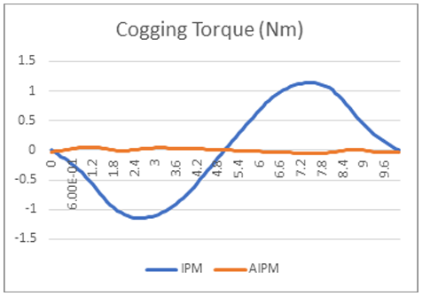
Fig. 3. Cogging Torque Measurement via EMWorks2D
Average Torque
To analyze the behavior of the machine, the average torque has been measured at different operation points with a specific current angle. The figure below shows the basic concept of torque production in synchronous machines.
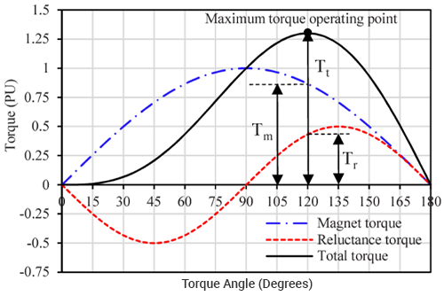
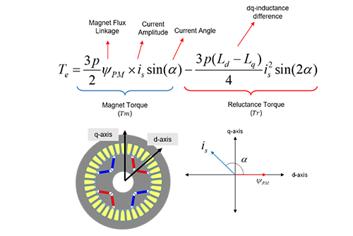
Fig. 4. Output Torque Components of the Synchronous Machines Including IPMSMs.
The average torque of the machine consists of two components. First is the torque produced by the interaction of magnets and the stator field (Magnet torque) and the second is the result of iron core attraction to the stator field (reluctance torque). By this means, it is possible to monitor the magnet torque and reluctance torque components and observe their changes over various current angles. The figure below illustrates the measured torque values for both symmetric and asymmetric structures. As demonstrated, while the magnetic torque of the asymmetric design is lower than the symmetric one, the total torque of the asymmetric design is higher (14.16 Nm) compared to the symmetric design (13. 88 Nm). The reduction of magnet torque is a result of magnet material reduction while the increase of total torque is due to the improvement of reluctance torque using the asymmetric arrangement of barriers.
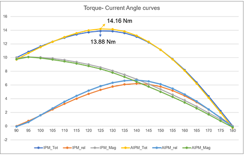
Fig. 5. Measured Torque Versus Current Angle Curves
Torque Ripple
By adopting the asymmetric design approach, the ripple rate of the torque waveform can be significantly reduced. The figure below shows the reduction of the ripple rate from 73.93% (symmetric) to 19.19% (asymmetric). The ripple rate depends on various factors including airgap flux harmonics, cogging torque, stator’s time harmonics, and iron core saturation. The asymmetric design directly affects the airgap flux harmonics. As a result, it is possible to minimize the ripple rate based on rotor asymmetricity.
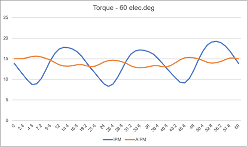
Fig. 6. The Torque Waveform of Symmetric and Asymmetric Designs and MTPA Operation
Conclusion
In this application note, the effects of asymmetric design on an IPMSM have been studied. For study purposes, the EMWorks2D simulation environment has been used as the main tool for No-load and full-load performance analyses. Two different models (symmetric and asymmetric) have been generated. The study showed that the characteristics such as cogging torque and ripple rate can be significantly reduced. Meanwhile, it is also possible to reduce the magnet volume and simultaneously increase the average toque of the IPMSM.
References
[1] G. Lei, J. Zhu, Y. Guo, C. Liu, and B. Ma, “A review of design optimization methods for electrical machines,” Energies, vol. 10, no. 12, 2017, doi: 10.3390/en10121962
[2] W. Ren, Q. Xu, Q. Li, and L. Zhou, “Reduction of Cogging Torque and Torque Ripple in Interior PM Machines with Asymmetrical V-Type Rotor Design,” IEEE Trans. Magn., vol. 52, no. 7, pp. 3–7, 2016, doi: 10.1109/TMAG.2016.2530840