PIFA Antenna - Design and Simulation
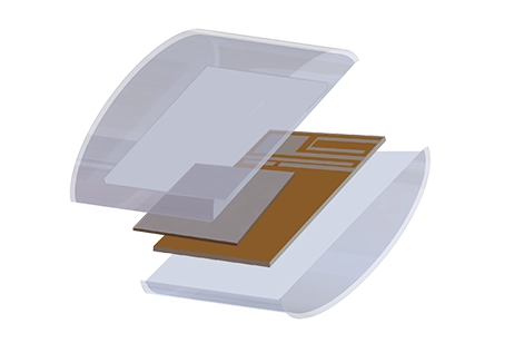
The mobile phone sector demands compact, efficient antennas for enhanced communication. Planar Inverted F Antennas (PIFA) stand out for their small size and user safety, directing radiation away from the user. This article highlights HFWorks' capabilities in designing, simulating, and optimizing dual-band PIFA antennas for GPS and WiMAX. It showcases a PIFA antenna model featuring driven (C-shaped patch and shorting strip) and parasitic (shorted rectangular patch) elements, designed for optimal performance over a finite ground plane with air substrate, as demonstrated in Figure 1.
Figure 1 - 3D model of a PIFA antenna
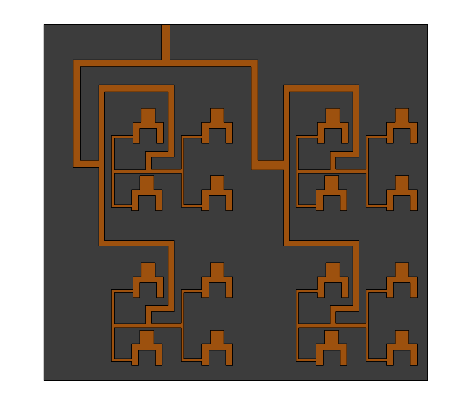
Figure 2 illustrates the dual-band antenna's schematic, featuring a 50 Ohm coaxial feed line for excitation. Electrical parameters for such structures can be accurately calculated using ATLASS, showcasing the antenna's design and functionality.
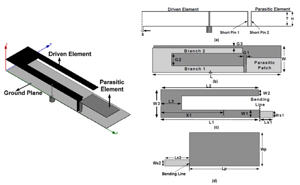
Figure 2 - Schematic diagram of the PIFA antenna
To streamline the design process, geometrical parameters are set in a file and imported into the CAD software as equations, with key details summarized in Table 1.
Table 1- Geometric parameters of the PIFA antenna
| Variable | Value (mm) | Variable | Value (mm) |
| L | 100 | W3 | 22 |
| W | 24 | Ls1 | 9.5 |
| H | 9.7 | Ws1 | 5 |
| T | 9.3 | Ls2 | 9.5 |
| S | 1 | Ws2 | 2.5 |
| G1 | 2 | Lp | 27 |
| G2 | 11 | Wp | 13 |
| G3 | 2 | Lg | 99 |
| L1 | 71 | Wg | 24 |
| L2 | 70 | X1 | 45 |
| L3 | 15 | X2 | 44 |
| W1 | 6 | Y | 1 |
| W2 | 5 |
Simulation Results
Figure 3 presents the simulated S-Parameters of the PIFA antenna via HFWorks, demonstrating operation at 1.595 GHz with a -26.90 dB reflection coefficient and at 3.363 GHz with a -45.96 dB reflection coefficient. The lower mode achieves a 90MHz impedance bandwidth, and the higher mode a 135MHz bandwidth, meeting the bandwidth needs for GPS and WiMAX applications.
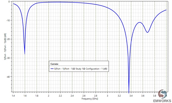
Figure 3 - Return loss of the PIFA antenna (dB)
The far-field simulation reveals how the field disperses around the model from a distance. Figure 4 displays the 3D gain pattern at the first resonance frequency of 3.363 GHz, while Figure 5 depicts this gain pattern in 2D, offering a comprehensive view of the antenna's performance.
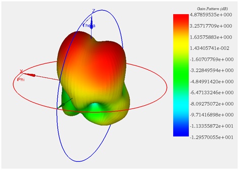
Figure 4 - 3D plot of the gain pattern at 3.363 GHz
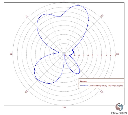
Figure 5 - 2D plot of the gain pattern at 3.363 GHz
Parameterization
To explore how altering the length of the metal strip (L3) between branch 1 and branch 2, as shown in Figure 2, impacts the S parameters, HFWorks enables designers to simulate various scenarios. This flexibility ensures optimal performance by understanding parameter effects on outcomes. HFWorks' integration with CAD software allows for direct model simulations, avoiding data re-importation after design changes. Figure 6 demonstrates that reducing L3 barely affects the GPS band's impedance bandwidth but worsens impedance matching, due to increased overlap between branches and the driven element's ground plane.
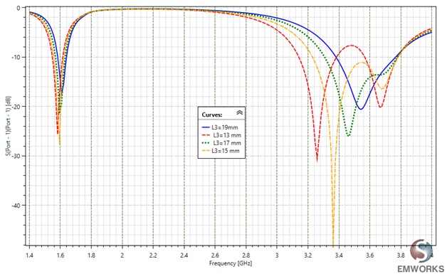
Figure 6 - Return loss as a function of dimension, L3 of a PIFA antenna
This variation in the area leads to an increase in capacitive reactance, consequently reducing resonant frequencies within the WiMAX band. Notably, as length L3 decreases, the WiMAX band's bandwidth surprisingly expands while maintaining a consistent higher frequency. Moreover, with L3 values below 15 mm, a wide band spectrum disappears, giving rise to a dual-band behavior. This observation sheds light on the antenna's behavior under different L3 configurations.
Conclusion
This application note delves into the design and simulation of dual-band Planar Inverted F Antennas (PIFA) for mobile communication, specifically targeting GPS and WiMAX applications. Utilizing HFWorks for simulation, the note presents a compact and efficient PIFA model that emphasizes user safety by directing radiation away from the user. The antenna features a unique combination of driven (C-shaped patch and shorting strip) and parasitic (shorted rectangular patch) elements, optimized for performance across dual bands on a finite ground plane with air substrate.
Simulation results reveal the antenna's proficiency in operating within the desired frequency ranges, demonstrating significant reflection coefficients at both 1.595 GHz and 3.363 GHz, with adequate impedance bandwidths for GPS and WiMAX. Far-field simulations provide insights into the antenna's gain patterns, illustrating its effectiveness in dispersing the field around the model.
Further parameterization studies illustrate the impact of altering the length of the metal strip (L3) on the S parameters, highlighting HFWorks' capability to simulate various scenarios for optimal design. This flexibility in adjusting geometrical parameters directly within the CAD software streamlines the design process, allowing for efficient exploration of design changes without the need for data re-importation.
References
[1] https://www.emworks.com/product/ATLASS
[2] Mayank Agarwal, Rajesh Singh, and Manoj Kumar Meshram " Dual-Band Linearly Polarized Planar Inverted-F Antenna (PIFA) for GPS/WiMAX Applications", presented at Students Conference on Engineering and Systems (SCES), 2013 IEEE.