External Rotor PMSM
In response to urgent environmental concerns, there's a growing push to reduce carbon emissions and adopt sustainable energy solutions. Electric machines, crucial for achieving a carbon-neutral future, are widely applied, from electric vehicles to renewable energy generation. Permanent Magnet Synchronous Machines (PMSMs), known for their efficiency and power density, play a significant role in these efforts. Research on external rotor PMSMs aims to enhance efficiency, explore new materials, and optimize design parameters for effectiveness and feasibility. These machines, commonly used in electric vehicles, offer efficiency, low maintenance, and reduced noise and vibration. This study explores the design stages of an external rotor PMSM using FEM 2D software, EMWorks2D, analyzing power, torque, rotational speed, cogging torque, and torque ripple, with a focus on numerical calculations regarding variations in magnet pole arc coefficient sizes.
CAD Model
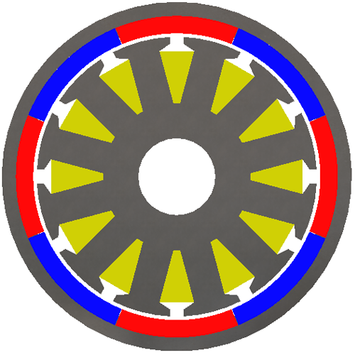
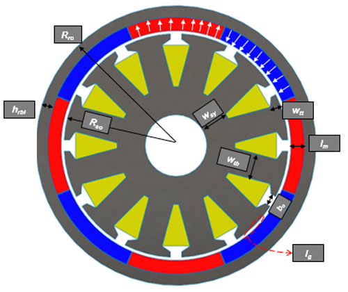
Improving cogging torque in PMSMs is vital for efficiency and noise reduction. Using EMWorks2D software, we simulated an external rotor surface PMSM, varying the magnet pole arc from full pitch to 31°. See Figure 1 for the structure with a full-pitch magnet pole arc.
Design Specification of the Studied Topology
The first step of the design is to generate the required parameters which are divided into 2 categories: PMSM specification mentioned in Table 1 and geometric design variables shown in Table 2 [6].
| PMSM Specification | value |
| Rated Power (W) | 100 |
| Rated Speed (rpm) | 750 |
| Rated Voltage (V) | 12 |
| Stator Slots Number | 12 |
| Rotor Poles Number | 8 |
| Parameter | Symbol | Unit | Value |
| Rotor Outer Radius | Rro | mm | 25 |
| Stator Outer Radius | Rso | mm | 20 |
| Rotor Back Yoke Thickness | hrbi | mm | 2 |
| Stator Back Yoke Thickness | wsy | mm | 5 |
| Tooth Body Thickness | wtb | mm | 4.5 |
| Tooth Tip Thickness | wtt | mm | 2 |
| Magnet Thickness | lm | mm | 2.5 |
| Slot Opening Width | bo | mm | 2 |
| Air-Gap Thickness | lg | mm | 1 |
| Axial Length | la | mm | 50 |
| Interpole Thickness Between 2 Successive Magnets |
I | mm | 1.5 |
According to the mentioned variables, the 2D design of the studied machine is presented as follows. The arrows’ direction in each magnet pole indicates its polarity. For this topology, the slot pitch is equal to 30° and the pole pitch is 45°. Consequently, the variation of the magnet pole arc is done from 45° to 31° by step of 2°.
Figures 3 and 4 show an explanation of the surface magnet pole arc variation. It is done from full pitch to 31° by step of 2°. For no full pitch magnet pole arc, the studied structure may resemble inset PMSM. Whereas, it is a surface PMSM where the height of the inter-pole is lower and does not align with magnet’s height.
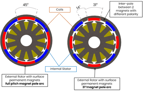
Fig. 3. Topology Specification: 12 Slots- 8 Poles External Rotor Surface PMSM for 2 Cases of Magnet Pole Arc Measure
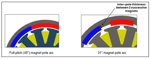
Fig. 4. Magnet Pole Arc Variation and Inter-Pole Presentation
For the material used, Neodymium is used for the permanent magnets having 1.12 T remanence and presenting a relative permeability equal to 1.05. For the iron core loss, AISI 1010 steel is used. It is a preferred material for stator and rotor yoke thanks to its saturation magnetic flux density which can reach 2.4T.
EMWorks Simulation Settings
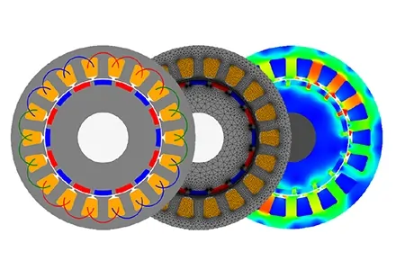
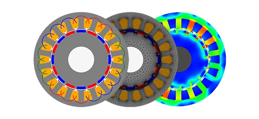
Following machine design completion, an EMWorks2D study (Figure 5) is outlined, involving key steps:
-
Applying materials to components.
-
Setting boundary conditions.
-
Applying virtual work.
-
Ensuring mesh control.
-
Determining windings for the PMSM.
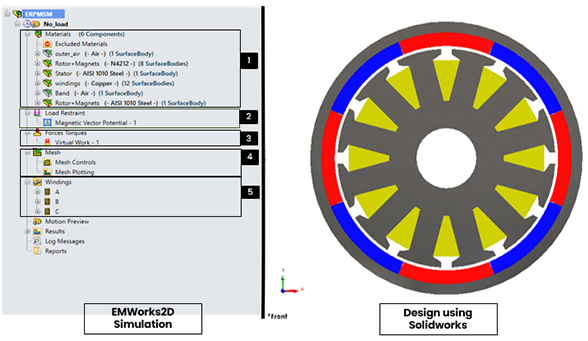
Fig. 5. EMWorks2D Study Details
Results and Discussion
The external rotor PMSM operational aspects for different magnet pole arc values are simulated and analyzed and the results are displayed below.
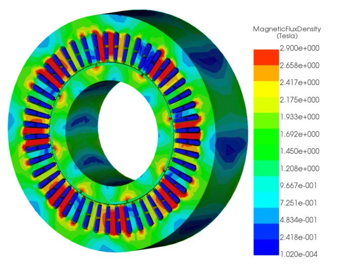
Magnetic Flux Density
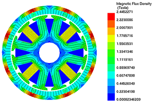
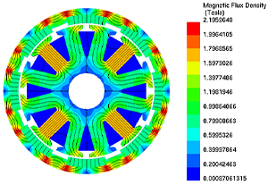
Figure 6 presents the magnetic flux density in the studied PMSM for full pitch and 31° magnet pole arc. It is clear that the magnetic fields are widely spread across the opening poles due to the inter-pole. The inter-pole, acting as an electromagnetic conductive material, facilitates the dispersion of the electromagnetic field within its region and effectively mitigates the saturation concentrated between the two magnet poles.
 |
 |
| (a) | (b) |
Fig. 6. 2D Maps of Magnetic Flux Density of the External Rotor PMSM: (a) Machine with Full Pitch Magnet Pole Arc, (b) Machine with 31° Magnet Pole Arc
Cogging Torque
The cogging torque was simulated for each magnet pole arc from 45° to 31° under open circuit conditions as shown in Figure 7. It can be observed that the cogging torque is high for different magnet pole arc values until it reaches 33°. It was balanced between 0.39 N.m and 0.49 N.m. For 33°, the cogging torque is equal to 0.26 N.m. The optimal value of the cogging torque, 0.067 N.m, is obtained when the magnet pole arc is equal to 31° (Figure 8).
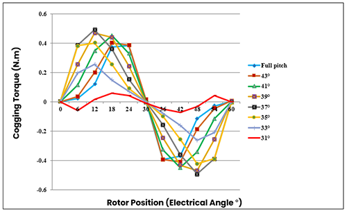
Fig. 7. Cogging Torque Produced by the External Rotor PMSM by Varying Magnet Pole Arc Across Different Rotor Positions
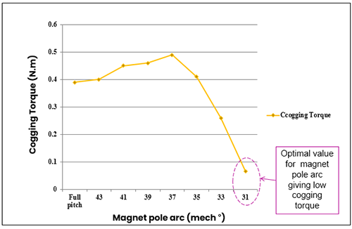
Fig. 8. Cogging Torque Produced by the ERPMSM by Varying Magnet Pole Arc
Back EMF and Output torque
Back EMF for one phase for both full pitch and 31° magnet pole arc is presented in Figure 9. The back EMF for full pitch is more trapezoidal compared to 31° magnet pole arc. This is explained by the presence of higher harmonics numbers compared to 31° magnet pole arc design. Harmonics values are estimated by using Fast Fourier Transform (FFT) as illustrated in Figure 10. Higher harmonics affect the sinusoidal formation after summation contributing to a trapezoidal waveform. A more sinusoidal phase EMF contributes to less noise, vibration and fewer ripples. Figure 11 presents the output torque results of each studied machine which are regrouped in Table 3. The output torque for both machines is practically the same having a value of 0.88 N.m. Whereas, it presents a high percentage of torque ripples of 94.38% for full pitch magnet pole arc and a low value of 17.04% for 31° magnet pole arc.
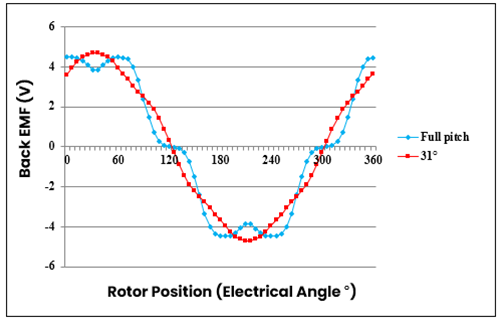
Fig. 9. Back EMF According to Rotor Position for Full Pitch & 31° Magnet Pole Arc
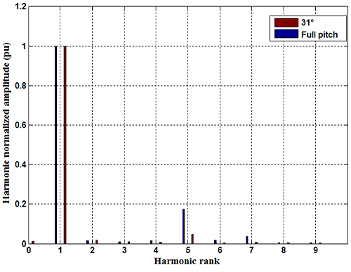
Fig. 10. FFT of Back-EMF for the Studied Cases
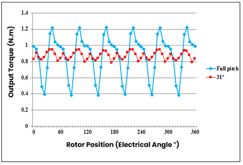
Fig. 11. Output Torque as Function as Rotor Position for PMSM with Full Pitch and 31° Magnet Pole Arc
| Magnet Arc | Average Torque (N.m) | Torque Ripple (%) |
| Full Pitch | 0.89 | 94.38 |
| 31° | 0.88 | 17.04 |
Table 3. Output Torque and Torque Ripples Calculation for the Studied Machines
Conclusion
The machine operational aspect for each of the reduced magnet pole arc variances is simulated using EMWorks 2D software solution. The variation of the magnet pole arc affects the performance of the machine. By varying the magnet pole arc from full pitch to 31°, the cogging torque has the lowest value for 31° magnet pole arc equal to 0.067 N.m. The PMSM with full pitch magnet pole arc provides a high value of cogging torque equal to 0.39 compared to 0.067N.m. The back EMF waveform is destroyed for the machine with a full-pitch magnet pole arc. This is explained by the presence of harmonics with ranks 5 and 7. Whereas, the back EMF waveform is sinusoidal for the machine with a 31° magnet pole arc. This is explained by the absence of harmonics with a rank superior to 1. For the output torque, it presents a high percentage of torque ripples of 94.38% for full pitch magnet pole arc and a low value of 17.04% for 31° magnet pole arc. An optimal machine with the defined design specification and having a 31° magnet pole arc is retained from this study.
References
[1] ?ebkowski A. Design, Analysis of the Location and Materials of Neodymium Magnets on the Torque and Power of In-Wheel External Rotor PMSM for Electric Vehicles. Energies. 2018; 11(9):2293. https://doi.org/10.3390/en11092293
[2] W. Deng and S. Zuo, "Comparative Study of Sideband Electromagnetic Force in Internal and External Rotor PMSMs With SVPWM Technique," in IEEE Transactions on Industrial Electronics, vol. 66, no. 2, pp. 956-966, Feb. 2019, doi: 10.1109/TIE.2018.2821110.
[3] M. Soyaslan, Y. Avsar, A. Fenercioglu and O. Eldogan, "Cogging Torque Reduction in External Rotor PM Synchronous Motors by Optimum Pole Embrace," 2019 3rd International Symposium on Multidisciplinary Studies and Innovative Technologies (ISMSIT), Ankara, Turkey, 2019, pp. 1-4, doi: 10.1109/ISMSIT.2019.8932915.
[4]: T. Fan, Q. Li, Y. Li, X. Wen and X. Zhuang, "Influence of design parameters on characteristics of external-rotor permanent magnet synchronous machine," 2017 20th International Conference on Electrical Machines and Systems (ICEMS), Sydney, NSW, Australia, 2017, pp. 1-6, doi: 10.1109/ICEMS.2017.8055945.
[5]: Q. Li and T. Fan, "Torque Improvement of External-Rotor Permanent Magnet Machine Using Flux Concentrated Rotor," 2018 IEEE International Magnetics Conference (INTERMAG), Singapore, 2018, pp. 1-1, doi: 10.1109/INTMAG.2018.8508125.
[6]: Ling, P. P., Dahaman Ishak, and T. L. Tiang. "Influence of magnet pole arc variation on the performance of external rotor permanent magnet synchronous machine based on finite element analysis." 2016 IEEE International Conference on Power and Energy (PECon). IEEE, 2016.
[7]: Song, Yongda, et al. "Analysis and reduction of cogging torque in direct?drive external?rotor permanent magnet synchronous motor for belt conveyor application." IET Electric Power Applications 15.6 (2021): 668-680.