

Structural Coupling in EMWORKS
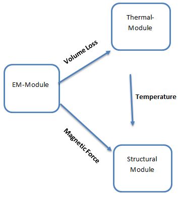
Structural coupling in EMWORKS links electromagnetic solvers with mechanical stress/deflection analysis. It lets you transfer electromagnetic forces, pressures, and losses to a structural or thermal–structural model to evaluate deformation, stress, and fatigue.
Map magnetic, electric, or Lorentz forces from EM analysis onto solid bodies
Compute resulting displacement, stress, strain, and safety factors
Assess stiffness, deformation, and contact behavior under electromagnetic loading
Key Features of EMWORKS Structural Coupling
1
Electromagnetic → structural load transfer: Map magnetic, electric, or Lorentz forces and pressures from EM analysis onto solid bodies or assemblies.
2
Static and modal stress analysis: Compute displacement, stress, strain, safety factor, and natural frequencies under electromagnetic loading.
3
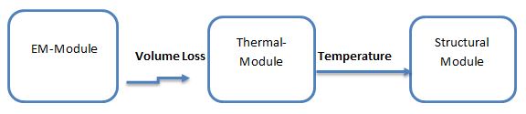
Thermo-mechanical coupling: Use EM losses (J·E, core loss, dielectric loss) as heat sources and evaluate thermally induced deformation and stress.
4
Multiphysics workflow: Electromagnetic → thermal → structural chaining in one environment for consistent geometry, mesh, and materials.
5
Material and geometry checks: Compare alternative materials and cross-sections against stress limits, stiffness targets, and fatigue constraints.
Applications for Structural Coupling
Electric machines (motors, generators)– Magnetic forces on teeth, yokes, and rotors; deformation, vibration, and noise risk.
Transformers and reactors – Core and winding forces under load, inrush, and short-circuit; clamping stress and tank loading.
Solenoids and actuators– Plunger/armature forces, contact impact, and housing deformation during operation.
Busbars, conductors, and rails – Electrodynamic forces under fault currents; mechanical support and bracing requirements.
Magnetic bearings and levitation systems – Stiffness, deflection, and stress in rotor and stator parts under electromagnetic loads.
High-power and HV equipment – Structural impact of electromagnetic forces and thermal expansion in switchgear, HV terminals, and clamps.
Results of EMWORKS Structural Coupling
Displacement
- Ux : Displacement in x direction
- Uy : Displacement in y direction
- Uz : Displacement in z direction
- Ur : The resultant displacement
Stress
- Von Mises Stress
- SXX : Normal stress in the X direction
- SYY : Normal stress in the Y direction
- SZZ : Normal stress in the Z direction
- SXY : Shear stress in the Y in the YZ plane
- SYZ : Shear stress in the Z in the XZ plane
- SZX : Shear stress in the Z in the YZ plane
- PS1 : First principal stress
- PS2 : Second principal stress
- PS3 : Third principal stress
- Stress intensity (P1-P3)
Strain
- Von Mises Strain
- EXX : Normal strain in the X direction
- EYY : Normal strain in the Y direction
- EZZ : Normal strain in the Z direction
- EXY : Shear strain in the Y in the YZ plane
- EYZ : Shear strain in the Z in the XZ plane
- EZX : Shear strain in the Z in the YZ plane
- PE1 : First principal strain
- PE2 : Second principal strain
- PE3 : Third principal strain
- Tresca
Reaction Force
- RFX : Reaction Force in the X direction
- RFY : Reaction Force in the Y direction
- RFZ : Reaction Force in the Z direction
3D Safety Factor
- Von Mises Stress Failure Criterion
- Maximum shear stress Failure Criterion
- Maximum Normal Stress Failure Criterion
- Mohr Coulomb Failure Criterion