Introduction
Current transformers are used to convert high primary currents into standardized low-level secondary currents suitable for measuring instruments, energy meters, digital relays, and protection equipment. Unlike conventional power transformers, a current transformer is designed to reproduce the primary current with a high degree of accuracy while maintaining electrical isolation between the power circuit and the measuring devices. Industrial current transformers are commonly installed in substations, switchgear assemblies, motor control centers, renewable energy systems, industrial plants, and commercial distribution networks. Depending on the application, a CT may be optimized for precision metering, protection, or both. Metering current transformers prioritize ratio and phase accuracy within the normal operating range, while protection current transformers are designed to remain functional during fault conditions without excessive saturation. The electromagnetic performance of a current transformer depends on several design parameters. Core dimensions, magnetic material properties, winding configuration, burden impedance, operating frequency, and primary current all influence the magnetic flux distribution and the resulting secondary current. Although analytical equations provide useful initial estimates, they cannot accurately represent nonlinear magnetic behavior, localized saturation, leakage flux, or complex geometries. Finite element analysis (FEA) overcomes these limitations by solving Maxwell's equations throughout the entire computational domain. Instead of relying on simplified assumptions, FEA computes the magnetic field distribution at every point inside the transformer, providing detailed information about flux density, magnetic field intensity, induced voltage, and current distribution. This enables engineers to evaluate multiple design alternatives, optimize performance, and reduce the need for costly physical prototypes. In this application note, a 400/5 A toroidal current transformer is modeled and analyzed using EMWORKS EMAG 3D. The simulation investigates the magnetic behavior of the transformer under rated operating conditions and demonstrates how finite element analysis can be used to evaluate the overall electromagnetic performance of the design.
1. Operating Principle of a Current Transformer
A current transformer operates according to the principle of electromagnetic induction. The primary conductor, which carries the line current, passes through the magnetic core and produces a time-varying magnetic field. This magnetic field establishes an alternating magnetic flux inside the core.
The changing magnetic flux induces a voltage across the secondary winding according to Faraday's law of electromagnetic induction. When the secondary circuit is connected to a burden(load), the induced voltage drives a secondary current whose magnitude is proportional to the primary current.
For an ideal current transformer, N_p * I_p = N_s * I_s
where
- (N_p) = number of primary turns
- (N_s) = number of secondary turns
- (I_p) = primary current
- (I_s) = secondary current
Since most industrial current transformers use a single conductor as the primary winding, the primary typically consists of one turn.
Consequently, the current ratio is determined primarily by the number of secondary turns. For the transformer investigated in this study,
I_p/I_s= 400/5=80
Therefore,
N_p=1
N_s=80
This winding configuration produces the desired 400/5 A transformation ratio under rated operating conditions.
Unlike power transformers, current transformers should always operate with the secondary winding connected to an appropriate burden or a short circuit. Opening the secondary circuit while current flows in the primary may generate dangerously high voltages across the secondary terminals and significantly increase the magnetic flux inside the core. Therefore, selecting an appropriate burden is an important part of the design process.
Design Specifications
A toroidal current transformer was selected for this study because of its compact structure, low leakage flux, and excellent magnetic performance. The core dimensions were chosen by initial analytical calculation to provide sufficient magnetic cross-sectional area while maintaining low operating flux density under rated conditions.
The primary winding consists of a single conductor passing through the center of the toroidal core. The secondary winding contains eighty distributed turns around core, producing the required current transformation ratio of 80:1.
The nonlinear magnetic characteristics of core material are included in the finite element model to accurately capture the core behavior near the operating point.
The dimensions of the current transformer core were selected based on the required nominal operating conditions, including the 400 A primary current, 5 A secondary current, 50 Hz operating frequency, and 15 VA secondary burden. The core cross-sectional area and magnetic path length were calculated to maintain the flux density within the safe operating range of the selected core material while ensuring accurate current transformation. Based on these analytical calculations, the final core dimensions, winding configuration, and electrical parameters were obtained. In the following simulation, the complete CT model with these final design parameters was implemented in EMWORKS EMAG 3D to evaluate the accuracy of the analytical design and verify the electromagnetic performance, including flux distribution, core operating point, and secondary current response under rated conditions.
Due to the importance of considering the end effects and leakage flux, a 3D simulation was necessary for this geometry.
Table 1. Current Transformer Design Specifications
Parameter | Symbol | Value |
| Transformer Type | — | Toroidal Current Transformer |
| Rated Primary Current | (I_p) | 400 A |
| Rated Secondary Current | (I_s) | 5 A |
| Current Ratio | (I_p/I_s) | 400/5 A |
| Primary Turns | (N_p) | 1 |
| Secondary Turns | (N_s) | 80 |
| Operating Frequency | (f) | 50 Hz |
| Core Cross-Sectional Area | (A_c) | 1190 mm² |
| Mean Core Radius | (r_m) | 215 mm |
| Approximate Magnetic Path Length | (l_m) | 1.35 m |
| Secondary Burden | (S_b) | 15 VA |
| Burden Resistance | (R_b) | 0.6 Ω |
| Core Material | — | Grain-oriented silicon steel |
2. Geometry, Material Definition, and Simulation Setup
2.1 Current Transformer Geometry
The current transformer was modeled as a mentioned in the previous section. The modeled geometry in the EMAG using Autodesk Inventor is shown below.
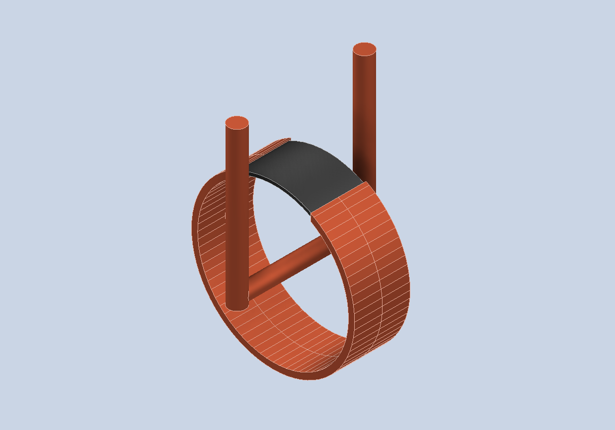
The selected geometry provides a closed magnetic path, which minimizes leakage flux and improves current transformation accuracy.
The finite element model includes the following regions:
- Toroidal magnetic core
- Primary conductor
- Secondary winding region
- Surrounding air domain
2.2 Core Material Properties
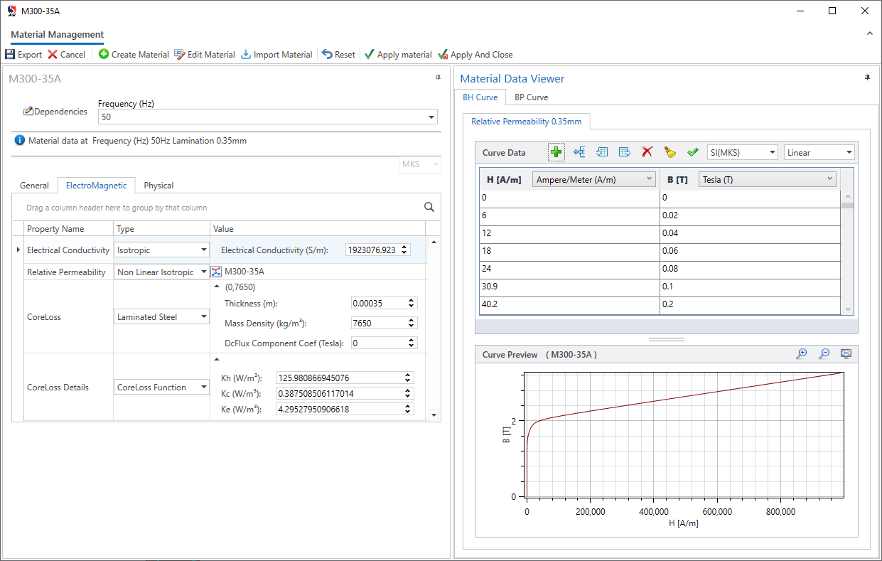
The magnetic core was assigned a nonlinear Grain-oriented silicon steel. Using the nonlinear B–H characteristic is essential for accurately predicting the operating point of the core and identifying possible saturation regions.
The material definition includes:
- Nonlinear B–H curve
- Electrical conductivity
- Core-loss coefficients
These properties enable the solver to account for the magnetic behavior of the core under alternating excitation.
2.3 Winding Configuration
The primary winding consists of a single conductor carrying the rated current of 400 A with sinusoidal wave form. The conductor passes through the center of the toroidal core and therefore represents one primary turn.
The secondary winding contains 80 turns, which produces the required 400/5 A transformation ratio. The winding was defined as a stranded coil with an external resistive burden connected to the secondary circuit.
Table 2. Winding parameters
Parameter | Value |
Primary turns | 1 |
Secondary turns | 80 |
Primary current | 400 A |
Rated secondary current | 5 A |
Burden resistance | 0.6 Ω |
2.4 Mesh Generation
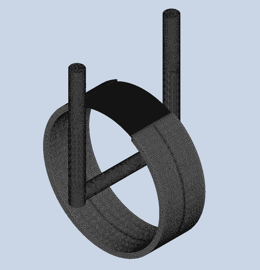
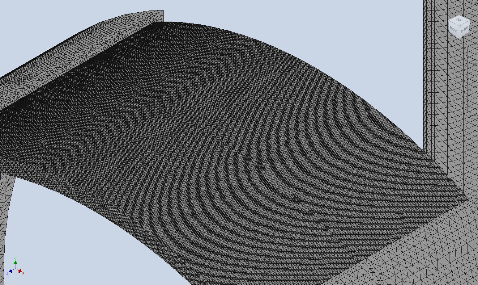
An accurate finite element mesh was generated automatically by the software. Additional refinement was applied in regions where higher field gradients were expected.
Refined mesh regions include:
- Magnetic core
- Primary conductor
- Secondary winding region
- Core-air interfaces
2.5 Simulation Settings
The electromagnetic analysis was performed using the AC magnetic and transient magnetic solver in EMWORKS EMAG.
After defining the geometry, materials, windings, external circuit, boundary conditions, and mesh settings, the model was solved to obtain the magnetic flux distribution, induced voltage, secondary current, and core operating characteristics.
3. Results and Discussion
After solving the model, the software provides a comprehensive view of the electromagnetic behavior of the current transformer. The post-processing tools allow the magnetic field, current distribution, and electrical quantities to be evaluated under rated operating conditions.
3.1 Magnetic Flux Density
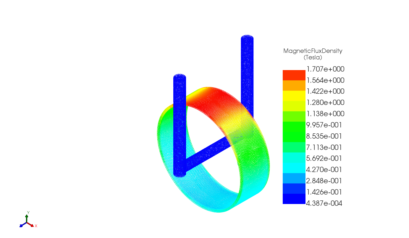
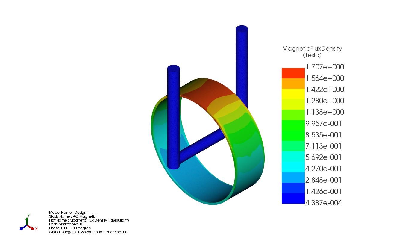
The magnetic flux density distribution confirms that the magnetic flux follows the toroidal core with very low leakage flux. As expected, the highest flux density appears along the magnetic path of the core, while the surrounding air region carries only a small portion of the magnetic field.
The maximum flux density remains below the saturation limit of the selected silicon steel, indicating that the transformer operates within its linear region at the rated current.
3.3 Magnetic Field Intensity
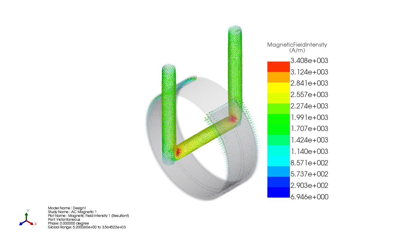
The magnetic field intensity is highest near the primary conductor and decreases throughout the core. The field distribution agrees with the expected operating characteristics of a toroidal current transformer.
3.4 Secondary Current
The results show that the secondary current closely follows the expected 5 A value under rated conditions. This confirms that the selected winding ratio and burden provide the desired current transformation.
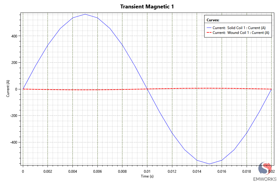
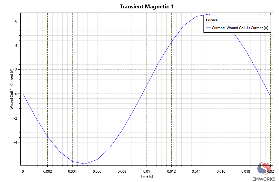
Due to the large current ratio of the current transformer, plotting the primary and secondary currents on the same graph does not provide a clear visualization of the secondary current waveform. Therefore, the secondary current is plotted separately to better examine its waveform and phase relationship. As shown in the figure below, the secondary current is a pure sinusoidal waveform and exhibits a phase shift of approximately 180° with respect to the primary current, as expected for the selected current direction and winding polarity.
3.5 Core Saturation
The nonlinear material model makes it possible to identify regions approaching magnetic saturation. Under the rated 400 A primary current, no significant saturation is observed, indicating sufficient core cross-sectional area for normal operation.
Higher primary currents can be simulated to determine the saturation point and evaluate the transformer's performance during fault conditions.
To determine the maximum linear operating current of the current transformer (CT), an Optimetrics parametric sweep was performed in AC Magnetic solver by varying the primary current from 0 A to 10,000 A. For each operating point, the induced secondary current was calculated, and its amplitude was extracted from the simulation results. This approach makes it possible to evaluate the CT response over its complete operating range and identify the point at which the secondary current begins to deviate from the expected linear relationship with the primary current due to core saturation.
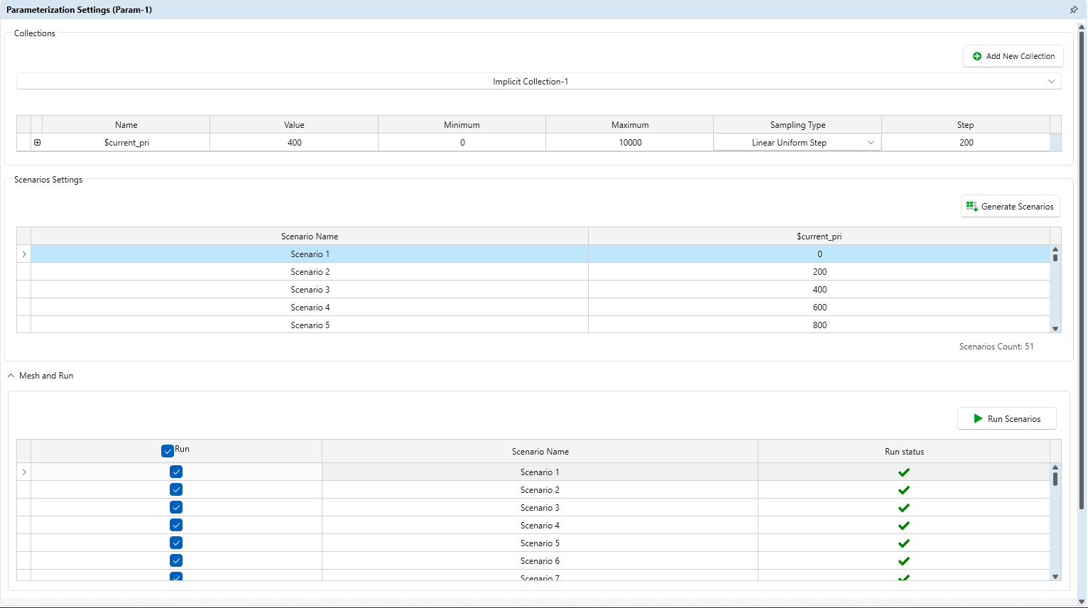
The amplitude of the secondary current as a function of the primary current is shown in the figure below. In the linear region, the secondary current increases proportionally with the primary current. As the magnetic core approaches saturation, this proportional relationship gradually deteriorates, allowing the maximum linear operating current of the current transformer to be identified.
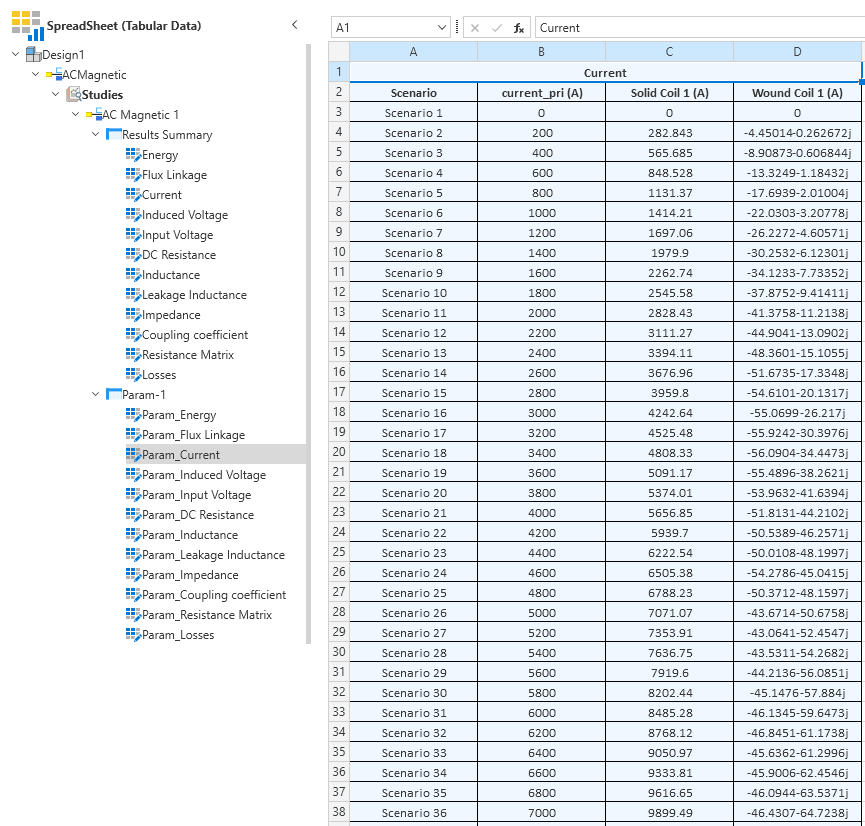
The output (secondary) current versus the input (primary) current was extracted from the Results Center. For improved visualization and easier identification of the linear operating region, the amplitude of the secondary current phasor is plotted against the primary current, as shown in the figure below
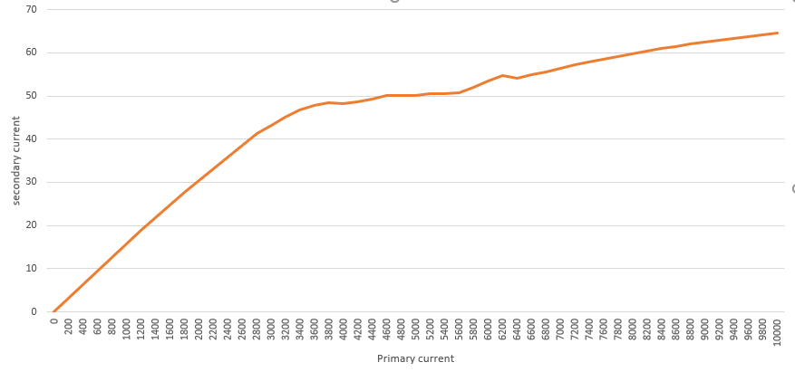
As shown in the results, this current transformer configuration remains linear up to approximately 3400 A of primary current. Beyond this operating point, the magnetic core begins to saturate, causing the secondary current to deviate from its linear relationship with the primary current.
3.6 Summary
The simulation verifies that the designed current transformer provides accurate current transformation while maintaining low magnetic flux density under rated conditions. Also with a primary current sweep, the linear operation region is extracted too. The finite element model also offers valuable insight into the internal magnetic field, helping engineers optimize the design before manufacturing.